0

I was looking for a similar solution to this question:

I want to generate a pulse (high) of 2 seconds when that DC supply is turned ON.

Is there a solution where we can implement this without using any microcontroller, timer IC or any delay IC? The circuit can contain resistors, capacitors, transistors or diodes etc.

The last answer was my approach, but this does not discharge the circuit when the power supply is taken away. So it only works once.

Picture stolen from last answer

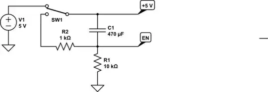
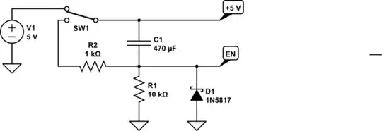
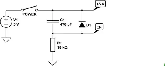
Is there an easy way to have the capacitor discharged (in less than 1 second) when the 'POWER' switch is opened again?

And with easy I mean with less components than this answer, which uses 8 resistors, a single capacitor and 4 transistors.

EDIT

The goal is to power a DC motor for maximum 2 - 10 seconds (adjustable with potmeter) every time the power is turned on. If the power gets turned off the motor will also stop running.

The actual load will be a 5W DC motor, but this will be done by using another transistor or mosfet.

Timing diagram:

                __________       __    ______
Power      ____|          |_____|  |__|      |_______
                ____             __    ____  
Motor      ____|    |___________|  |__|    |_________
                <--> = 2 s

EDIT

I edited the restrictions in the title because timer IC is being considered.

Egon
  • 11
  • 2
  • 1
    The many-components answer by Transistor is quite good; component count is good for what it does. If you want low partcount, why are you restricting timer ICs, they are perfect for these kinds of tasks? – anrieff Apr 02 '20 at 16:33
  • Is there something wrong with adding a resistor in parallel to your C1? That would discharge the capacitor over time, a time which you can set by selecting an appropriate resistor. – Marcus Müller Apr 02 '20 at 16:39
  • I have very little experience with electronics so i was looking for a circuit i understand. But maybe i should look into this timer IC solution.

    Thanks for your comment. @anrieff

    – Egon Apr 02 '20 at 16:40
  • @Marcus Müller Would this not change the charging time and voltage left over R1? – Egon Apr 02 '20 at 16:43
  • yes, but you're in charge of R1, too :) – Marcus Müller Apr 02 '20 at 16:43
  • @Marcus Müller, Do you have any reference on the timing and voltage calculations if i would use your solution? Or can i assume that adding a smaller resistor (say 1% of the R1 resistance) will not affect this much? – Egon Apr 02 '20 at 16:47
  • @Egon Well, you need either simulate the transient behaviour, or just solve the differential equation that gives you the EN voltage, by hand, when you switch on the 5V. Same for when you switch it off. SPICE is your friend. Many variants, LTSpice, ngspice... – Marcus Müller Apr 02 '20 at 16:50

2 Answers2

1

One way to reset the capacitor is to use a double throw switch.

schematic

simulate this circuit – Schematic created using CircuitLab

This circuit has a feature that may be problematic, depending upon what the +5V and EN nodes are connected to. C1 will hold its charge for a short time. If the +5V node falls much more rapidly than C1 discharges, the EN node could go negative. Therefore, it may be useful to add a clamping diode between the EN node and ground, to keep the node from going too negative.

schematic

simulate this circuit

I used a Schottky diode for a low forward voltage. However, Schottky diodes tend to have significant reverse leakage, and this will affect the timing of the RC circuit. Choose a diode that fits your needs.

Math Keeps Me Busy
  • 23,260
  • 4
  • 21
  • 75
-1

schematic

simulate this circuit – Schematic created using CircuitLab

Figure 1. A faster discharge can be obtained with D1.

The true answer depends on what the load is. If, for example, your circuit draws 1 mA then the capacitor will discharge at a rate given by \$ \frac {dV}{dt}= \frac I C = \frac {1m}{470\mu} = 2 \ \text {V/s} \$.

If you give more details in your question we can help further.

Transistor
  • 175,532
  • 13
  • 190
  • 404
  • i added some details to the question. will your answer (adding a diode) do the trick? – Egon Apr 02 '20 at 17:14
  • 1
    You've made it into an entirely different question. The one you linked to was to apply a very low-current pulse to a microcontroller. (1) What What parts have you got to hand? (2) What is the motor voltage? (3) I've added a timing diagram to your question. Please check that you understand it and that it's correct. – Transistor Apr 02 '20 at 17:28
  • I thought using another transistor or mosfet to power the motor would ask only a low-current pulse on the gate?

    I have:

    • 4.5V source (3 AA battery)
    • some mosfets, transistors, capacitors and resistors (i can buy for example the timer IC @anrieff suggested)
    • 6V 5W DC motor

    your timing diagram is exactly what i need

    – Egon Apr 02 '20 at 17:44
  • 1
    Are you assuming a load on the +5V line? Otherwise D1 does nothing. – Spehro Pefhany Apr 02 '20 at 17:50
  • 1
    @Spehro, yes. The question has evolved since originally posted. Ho-hum. – Transistor Apr 02 '20 at 18:02
  • I removed the IC restriction, if this makes a complete mess of this question (sorry), this question can be removed and i create a new one. – Egon Apr 02 '20 at 18:27
  • 3
    @Transistor Shouldn't D1 be across R1, anode to ground rather than across C1. –  Dec 24 '20 at 06:28