In a two input diode AND gate, when both inputs are low, both diodes conduct and pull the output down to a low voltage. How can the electrons flow to the input of the AND gate, when the input is connected to the - side of the battery?
Asked
Active
Viewed 239 times
2 Answers
2
simulate this circuit – Schematic created using CircuitLab
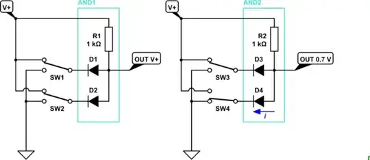
Figure 1. (a) AND with both inputs high. (b) AND with one input low.
You didn't post a schematic so we have to guess that this is the circuit you are talking about.
In a two input diode AND gate, when both inputs are low, both diodes conduct and pull the output down to a low voltage.
Yes and no. In a two input diode AND gate, when either input is low that diode conducts and pulls the output down to a low voltage.
How can the electrons flow to the input of the AND gate, when the input is connected to the - side of the battery?
Forget about electron flow and just use conventional current. The arrows in our diodes and transistors point in the direction of conventional current flow.
- With both switches up there is 5 V on both sides of the diodes and they don't conduct. OUT = 5 V.
- If either switch is connected to 0 V then conduction occurs and OUT = 0.7 V (the forward voltage drop, VF across the diode).
- Switching both to 0 V will still result in OUT = 0.7 V. (Diodes don't behave like resistors in parallel.)
Note that 'real' AND gates are not made like this. The pull-up resistor doesn't have good 'fan-out'. Fan-out is the maximum number of inputs one output can drive.
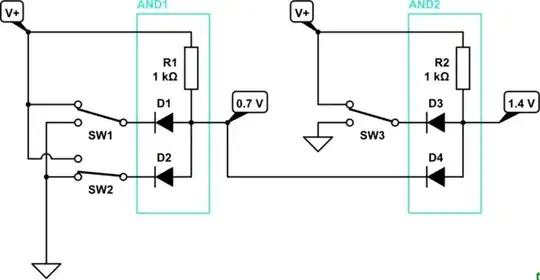
- If the following logic circuits draw power when high then the voltage at R1 will drop when two or more inputs are driven.
- If the following input was another of these AND gates then a LOW input voltage of 0.7 V would result in an output of 1.4 V on the following gate. At some point this is going to cause problems with logic levels.
Transistor
- 175,532
- 13
- 190
- 404
1
In the 2-input AND diode-resistor gate, the input diodes will conduct if the cathode is pulled at least one Vf (forward voltage, about 0.7V) threshold below the combined anode.
- one input pulled low to GND, the output is Vf.
- both Inputs pulled low, output is ... Vf.
In the second case the current from the pull-up resistor is simply divided between the two diodes. But the output doesn’t go below Vf.
(Conventional current flow is considered to be from positive to negative. This is opposite of electron flow. Blame Ben Franklin.)
hacktastical
- 53,912
- 2
- 49
- 152