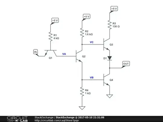
The first thing you need to do is realize that this is an "equivalent circuit", and not necessarily a manufacturing schematic. With that in mind, some things are pretty straightforward.
R1 limits the current which will be required to pull the input to ground. At this point, the base current will be about 1 mA. ((5 - 0.6)/4k). It's worth noting that the minimum low input current was specified at 1.6 mA, implying a collector current on the order of 0.6 mA, so Q1 was being driven quite hard.
R3 limits the current which will flow if the output is driven high but grounded. It is scaled to take into account the thermal performance of Q3 under these circumstances, allowing a grounded output to not kill the IC.
R2 provides base current to Q4 when the output is low. It is set by considering the performance of Q4. On the on hand, it needs to be as low as possible in order to provide maximum switching speed, but on the other hand it has to deal with the limitations of Q2 and Q4, which should be as small as possible in order to make the IC chip as small as possible. You need a small chip to increase yields, as early transistor processes had a very high defect rate, and a defect will make the gate unusable (and unsellable).
It also provides base drive to Q3 when the output is high. This doesn't actually work very well, given the limitations of the topology, and TTL gates had much lower ability to source current than to sink it.
Given R2 and Q4, R3 is chosen to provide a reasonable level of clamping for Q4 when the output is high, as you don't want leakage currents to turn Q4 on. It's probably the least critical value of the four resistors.
