Your present circuit's first stage will go rail to rail rather than amplifying your input signal. You can change it to:
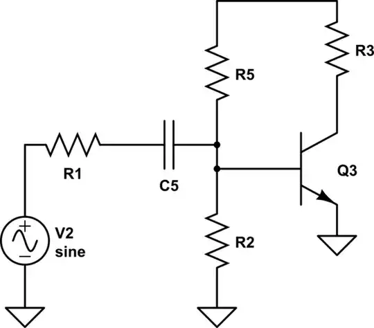
simulate this circuit – Schematic created using CircuitLab
The base of Q3 will always be near 0.7 volts, and you should think of your input to this transistor as an injected current rather than a voltage.
If you look at the second stage, consider what happens when Q1 is driving a positive current into the load, then the output swings negative. Q1 was "on" but as the voltage drops to a point where Q1 turns off (Q1 Vbe is less than 0.7), Q2 is off and doesn't turn on until the base of Q2 drops below 0.7 volts below the output. So there is a space where both Q1 and Q2 are off, and the amplifier supplies zero current. This is also fixable by a change in the bias:
simulate this circuit
Now you have no "dead zone" to pass through as your voltage swings.
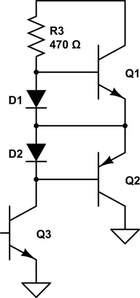
Finally we can get to your question. We can't let Q3 saturate, so the minimum voltage on Q3-collector is about 1.2 volts. Adding the base-emitter drop of Q2 of 0.7 volts, your output negative rail is 1.9 volts. We can't let Q1 saturate either, so we need 1.2 volts collector-to emitter, so your positive rail is (6 - 1.2) or 4.8 volts. So, your output swing is between 1.9 and 4.8 volts. We're assuming that by 160ma you mean +/- 160ma. At 4.8 volts output, your Q1 base voltage is 5.5 (4.8 plus the 0.7 base-emitter requirement). Your positive drive current into the base of Q1 can only come from R3 (no positive current can come from the collector of Q3). R3 has (6 - 5.5) or 0.5 volts across it, and you must supply 1 ma into the base. 470 ohms is not a bad choice!
When you are "pulling" (output current being pulled in by Q2) the requirement is different. Q3 collector minimum voltage is 1.2 volts to keep out of saturation, and we have added two 0.7-volt diodes, so your 470-ohm resistor has 3.4 volts across it. You need to pull down 1 ma for Q2 base, along with enough current to pull the 470-ohm resistor down (another 7.2 ma). So you need Q3 to be able to pull down 8.2 ma. If Q3 also has a gain of 160, your input signal has to be able to provide 51 uA into Q3 base to handle a 470-ohm value for R3.
You can play with the voltages and values and see the trade-offs.
Good Luck!
