1

I'm so confused. How does this chip drive 8 LED's when there is no apparent power source? What am I missing? Schematic
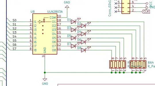
New design based on comments.

Updated Schematic

Kevin McQuown
  • 495
  • 3
  • 12
  • 1
    It doesn't. That circuit won't work. – Marcus Müller Dec 20 '19 at 18:25
  • What do I need to add? – Kevin McQuown Dec 20 '19 at 18:26
  • a sensible driving architecture, this is none. – Marcus Müller Dec 20 '19 at 18:27
  • 1
    Remove the ground on pin 10 and reverse the LEDs and it would work. – Kevin White Dec 20 '19 at 18:31
  • 1
    @KevinWhite ...and connect the other ends of the resistor networks RN3 and RN4 to some power supply voltage. – Elliot Alderson Dec 20 '19 at 18:34
  • so, honestly "keep all the components, but connect them quite differently, and maybe replace the central IC with something less overkill and 1970s". – Marcus Müller Dec 20 '19 at 18:35
  • The ULN is an NPN Darlington used only as low side switches with TTL level inputs.. You can drive indicators direct off any uC port as the driver RdsOn is low. Whoever did this? made a blunder. – Tony Stewart EE75 Dec 20 '19 at 18:36
  • ah, I see so the chip is sinking current. And yes, my inputs are from the HCT family of chips so I think this is the right approach – Kevin McQuown Dec 20 '19 at 18:37
  • your HCT can drive LEDs easily but HCT only defines the input threshold = 1.3V and makes no change to drive current. – Tony Stewart EE75 Dec 20 '19 at 18:38
  • OK, added my updated schematic. The LED's I'm driving are 0805's and need to be pretty bright for a wall display so I'm sinking about 20mA per LED which, I believe, is much more than the HCT family will provide. Seems like this Darlington Transistor Array could be perfect solution – Kevin McQuown Dec 20 '19 at 18:41
  • Updated diagram is OK. Connecting pin 10 to Vcc does no harm / MAY do some good. There are individual internal catch diodes for handling inductive transients - which you should not have here. || Always read the data sheet!!! || Note that Vcesat (fig 11) is going to be around 0.6V min / 1V max at 20 mA. || You don't say what Vcc is. With two series LEDS and Red LEDS you have marginal drive ability at Vcc=5V. With white LEDS and say only 1V resistor drop you'd need a minimum of 2 x Vf_LED + Vsat + Vres = 6 + 1 + 1 = 8V = marginal. 10V or 12V needed. At 12V you'd get Pres ~= 5V x 20 mA = 1W each – Russell McMahon Dec 20 '19 at 18:57

2 Answers2

2

The circuit is incorrect.
The IC provides 8 x Darlington drivers which provide switched low side drives.
The load needs to go from the IC to a positive supply.

ULN2803 data sheet here

The LEDs should be reversed and the resistor pack common connections should go to a positive LED supply voltage.
Pin 10 should be connected to LED supply positive - or can be left open-circuit for a resistive LOAD such as LEDs.

While modern "indicator LEDs" can be driven from typical microcontroller output pins, if higher currents are required a driver of this sort is "useful". Despite its 'time honoured' design it still does the job it was designed to do.

Drive current is specified as 500 mA/channel but average drive currents are usually limited by package dissipation. Quite useful drive current on all channels is possible with due care to thermal issues.
At 100 mA/channel drive, dissipation is around 100 mW - which may be acceptable without heatsinking. For the olde DIP package dissipation total is specified as 2.25W and 1W max per channel. So at 100 mW x 8, temperature rise at 55 C/W = 44 C above ambient.

Russell McMahon
  • 150,303
  • 18
  • 213
  • 391
1

ULN Darlingtons are low side NPN "hammer" drivers. You don't need a hammer.

For Indicators these days you don't need more than 1000mcd which can be 1 mA on a 20Cd LED rated at 20mA. However you could easily drive from the ports with 5 mA dissipating only < 2mW per port> .

The Current limiting R is just (5-Vf min)/ R.

You can choose either High side or Low side drive from CMOS.

Tony Stewart EE75
  • 1
  • 3
  • 54
  • 185
  • "If I had a hammer, I'd ... " :-) || He says he wants a wall display with about 20 mA/LED. – Russell McMahon Dec 20 '19 at 22:29
  • I'd still bet, I could pick a brighter LED using only 5 or 10mA because he forgot to say anything about luminous intensity or brightness in the question which tells me alot.... @RussellMcMahon but I think I got hammered at last nite's dinner party. – Tony Stewart EE75 Dec 21 '19 at 12:12