11

In particular I'm interested in SMD packages. A DIP package I would assume is simply put into a socket and programmed that way.

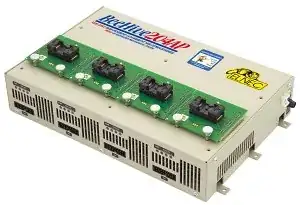
Of course you could get around this by designing a programmer header into the final product so the code can be uploaded and/or updated, but I know some companies sell pre-programmed chips (suppliers like Digikey offer this option, and from what I've heard you can sometimes contract with the OEM to supply pre-programmed chips). I'm just curious as to how they do this.

I have a two theories, but I don't think either of these are really practical and/or reliable.

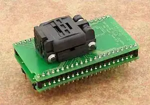
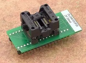
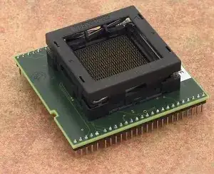
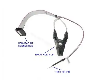
  1. Kind of "hold" the pin in contact with pads on a PCB, perhaps even use some sort of latch to ensure a solid contact. This would be similar to how DIP packages are programmed. Would work for packages with actual leads (QFP, SOIC, etc.), but I have doubts as to how well this works for BGA's or exposed pad type packages.

  2. Solder the part into place, program, then unsolder. Seems like it would subject chipsets to unnecessary thermal stress and would use a ton of solder/other resources.

helloworld922
  • 16,770
  • 10
  • 56
  • 88
  • http://solutions.3m.com/wps/portal/3M/en_US/Interconnect/Home/Products/ProductCatalog/Catalog/?PC_7_RJH9U5230O73D0ISNF9B3C3SI1000000_nid=H8M4M881C8itMXNM8F7WC9glLJ049RGKW5bl – The Photon Oct 31 '12 at 00:30
  • 1
    Manufacturers probe the chips before packaging, to test them and avoid packaging bad chips. They could also program at that time. But I guess you would need a large volume to make this economical. – markrages Oct 31 '12 at 20:45

3 Answers3

27

They make ZIF (zero-insertion-force) sockets for basically every package available.

Such as QFN:
enter image description here

Or SSOP:
enter image description here

And yes, they do make ZIF sockets for BGA devices.

enter image description here

And programmers that support many sockets at once:

enter image description here

Or for really large volumes, completely automated programmers with an integrated robot:

enter image description here

It's not hard to imagine how something like that could be adapted to a production-line robotic system, particularly when most modern MCUs don't actually need that many pins to be connected to be programmed.

Just google Production Programmer, and have a look around.


Disclosure: All the links here I just found via google. I have no actual experience with any of these companies.

Connor Wolf
  • 32,168
  • 6
  • 79
  • 138
11

Besides the ZIF socket programmer, another low-cost alternative for very low volume manual programming of SMD ICs is to use a SOIC or SOP Test Clip connected via IDC cable to the programmer board:

SOIC Test Clip

This method is used by hobbyists and small / low-budget production houses for short runs of microcontrollers or EEPROMS. The chip is gripped by the jaws of the clip, and requisite power and signal inputs are provided from the programmer board.

Anindo Ghosh
  • 50,446
  • 8
  • 105
  • 201
  • 1
    I'm pretty sure most low-volume hobbyist stuff is generally programmed in-circuit, with a pogo-pin setup (or something similar). – Connor Wolf Oct 31 '12 at 20:31
  • 1
    Given that SOIC test clips are reusable across projects and cost around $11 with the IDC cable wired in... also, not sure how a pogo pin solution can program an SMD IC not soldered in, ref the question. – Anindo Ghosh Oct 31 '12 at 20:38
  • 2
    Yep. I do exactly this for programming AVR Tiny13s. The board is too small for an ISP header and I don't do enough of them to warrant a pogo pin setup, so I hit on the idea of using a Pomona SOIC-8 clip that plugs into the jumpers from my JTAG-ICE II debugger. It works really well. – lyndon Nov 01 '12 at 01:03
3

For those of us at the bottom end of the hobby, a good tip, if you are unplugging the same DIP IC many times in order to program it separately from its final pcb, perhaps while developing a program, is to plug it into a DIP socket, and use that combination plugged into the pcb and the programmer. This save wearing and possibly bending or breaking the IC pins: if that happens to the DIP socket, well they are cheap enough. I also do this for an IC plugged into a breadboard. Here turned pin sockets are necessary to make good contact.

If wear on the socket on the pcb is likely to be a problem you could use a third DIP socket, and remove the IC plus its own DIP socket, leaving the two other sockets on the pcb.

I still have the first PIC I ever programmed, in 1996 -- a PIC16C84, which lost a pin (and suffered many other indignities like being plugged in the wrong way round) before I thought of this trick. It now has a wire soldered on to replace the pin, and it still works.

Harry Weston
  • 2,190
  • 3
  • 24
  • 28