1

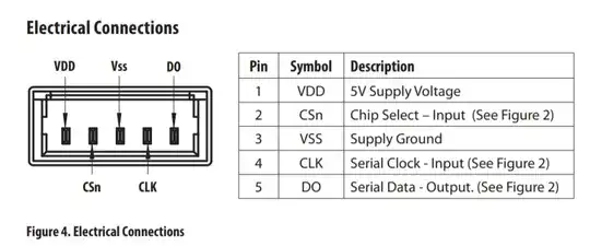
I have an AEAT-6010/6012 10/12-bit magnetic absolute encoder and it has the following pin-outs:

enter image description here

Since it is SSI but not SPI I dont use the CSn output and leave it.

I supply 5V to the encoder and clock it between 60kHz up to 100kHz but I dont get any expected data at DO pin. When I observe DO by a scope it is just a very low level clock signal but not any data stream expected.

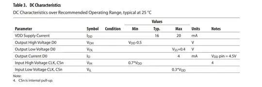
At one page it is mentioned that CSn is internal pull-up: enter image description here
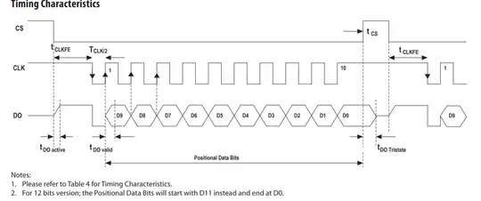
And unlike for a typical SSI this encoder also has a timing diagram for CSn:

enter image description here

When I measure CSn, it seems it is always 5V. Am I doing wrong by not using CSn here? Where and how should the CSn pin be connected? I'm really confused the interfacing of this pin and the function of it.
rdtsc
  • 16,238
  • 4
  • 32
  • 70
user1245
  • 4,125
  • 4
  • 38
  • 95

1 Answers1

1

Am I doing wrong by not using CSn here?

Yes, you are wrong by not using CSn. It is clear from the datasheet that this signal is required and must be driven low, with the timing shown in the diagram you supplied from the datasheet.

Where and how should the CSn pin be connected?

It would be driven by the same device (MCU?) which is driving the CLK signal (unless you are doing something very unusual).

SamGibson
  • 17,870
  • 5
  • 40
  • 59
  • Thanks yes I use the same MCU. But For CS to be driven LOW I need to connect CS to Vdd i.e. 5V isnt it? – user1245 Oct 24 '19 at 15:26
  • @atmnt - "I need to connect CS to Vdd i.e. 5V isnt it?" Due to the pull-up built into the sensor, no. The exact details will depend on your specific MCU and its GPIO voltage limits and configuration. You need to drive CSn low when required. It has a pull-up to the encoder's power supply (5V). I would configure an open-drain output on the MCU to drive CSn low - assuming your MCU's GPIO is 5V-tolerant. Also note that you must meet the timing requirements in the datasheet (Table 4 and Figure 2), when driving CSn and CLK. – SamGibson Oct 24 '19 at 15:34
  • I am guessing timing requirements doesnt matter(Im not sure) It seems it is to enable one of the multiple encoders. But I can try. My MCU at the moment is ATEMGA328P at the moment Im using the ArduinoNano board. I tried to connect CS to Vdd it didnt work. Can you link or make a small diagram how I can drive that CS down forever? – user1245 Oct 24 '19 at 15:37
  • Or should I just ground that pin ? I first want to try to drive down forever to test. Maybe timing is not necessary for a single encoder, – user1245 Oct 24 '19 at 15:42
  • @atmnt - "I am guessing timing requirements doesnt matter(Im not sure)" No, it really does matter! "I tried to connect CS to Vdd it didnt work." Yes, that will never work :-( Vdd = high, not low. "Or should I just ground that pin ?" That won't work after the first readout. "Can you link or make a small diagram how I can drive that CS down forever?" Won't work. Follow the datasheet. I don't know your experience, but have you used SPI before? Do you understand the difference between open-drain and push-pull outputs? How many SPI devices have you successfully interfaced before? – SamGibson Oct 24 '19 at 15:56
  • I used only one time SPI programmable poti. Okay now I will change my code for master then. I was not sure whether I should directly connect this CS to the one of the MCU(Nano) output pin(which will be ON OFF). ATMEGA328P is not open drain so can I just wire the CS to one of the digital pin to control enable? This open drain and push pull I read about them but when it comes to implement I wanted to be sure. – user1245 Oct 24 '19 at 16:03
  • Is your ATMETA328P powered from the same 5V supply as the encoder? If so, you can drive CSn with a push-pull output. Or you could just add an external transistor & resistor to convert the push-pull MCU output to an open-drain output (with a MOSFET) or open-collector output (with BJT). – SamGibson Oct 24 '19 at 16:14
  • Yes exactly same supply. Now I directly coupled CS to pin 4 which goes off and and on during data stream similar to the datasheet. I get data stream now. I just need to tweak it a bit(there is RC decay at the end of each datastream). Maybe I should add some scope screen shots later. – user1245 Oct 24 '19 at 16:19
  • "I get data stream now." Great - problem solved :-) "there is RC decay at the end of each datastream" Look at the datasheet. The DO signal goes tristate at the end of each position data output. I would probably add a pull-up resistor on DO. – SamGibson Oct 24 '19 at 16:23
  • Pull up or pull down? But the DO is input to the micro controller. It is not something like this https://cdn.sparkfun.com/assets/6/f/b/c/7/511568b6ce395f1b40000000.jpg DO is either 5V or 0V data stream. – user1245 Oct 24 '19 at 17:07
  • 1k pull down from DO to GND solved the issue – user1245 Oct 24 '19 at 17:11