3

I’ve been studying this book for digital electronics.

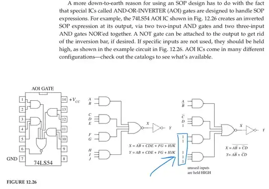
I think that the highlighted values in the operation of the shown AOI gate are not correct and should be 0 instead. enter image description here
Atom
  • 479
  • 4
  • 11
  • Did you make a truth-table to determine if the equations are correct? – Ron Beyer Sep 02 '19 at 14:54
  • In the 74LS (Low-power Schottky), unconnected inputs behave as if they are logical 1s, it is why the book says "unused input are held HIGH" and shows those 1s. – 比尔盖子 Sep 02 '19 at 15:06
  • 3
    I think you are right. (I could be pedantic and state that at least one input of each and-gate should be 0, but I will refrain from that). The expressions in the last picture are wrong and should state X = 0 and Y = 1. – Oldfart Sep 02 '19 at 15:14
  • I suspect it's a mistake in the book, from the logic expression, a single 1 output from an AND gate will make the NOR gate be 0 forever. – 比尔盖子 Sep 02 '19 at 15:19
  • 1
    Unfortunately an otherwise fairly good book is littered with typos and errors like the one you've spotted – NMF Sep 02 '19 at 21:41
  • @NMF: I am reading the book carefully and I reached page 46. I found 6 problems already. I also think it does a few lookaheads to concepts in future chapters, which cannot be understood by newcomers. I think the didactics is broken in some places, e.g. first explaining the ground symbol (page 41), half a page later say "this is the wrong one" and 5 pages later mention the correct one (page 46). Other example: measuring voltage but not considering direction (page 18), later (page 41) it suddenly matters. I didn't expect that in a 4th edition where there was likely a lot of time fixing errata. – Thomas Weller Feb 24 '21 at 08:57

1 Answers1

1

I think you are correct.

From the block diagram of the 74LS54 datasheet, it clearly shows a single "1" output from the AND gate would cause the next NOR gate be "0" forever.

74LS54 block diagram

比尔盖子
  • 6,750
  • 2
  • 27
  • 58