I need a transistor lesson that I could not find on the internet:
I have a standard GND-PNP-Load-(-20Vcc) arrange:
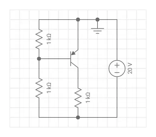
(The two resistors attached to the base are to form a divider - ignore the values).
Im struggling because if I leave the base floating (for testing purposes), the transistor conducts.
I tried making every thinkable voltage divider between GND and -20V to feed the base. The voltage on the base never goes above -0.65V, where (I suppose) it would cutoff.
Was it a NPN transistor, leaving a small voltage (<0.6) on the base would cut it off. Not here.
It's a BC556.
The transistor does work well on the linear region
The datasheet says ICBO is -15nA. Very low value. Does this change anything ?
Those schematics come from a humble simulator that doesn't allow me to tag the components.
I'm clearly missing a polarity rule or something. Who can point it out ?
Edit:
The schematic above was a simplification. After no success following your suggestions, I started to think that a simplification was not a good idea (probably the "load" messes with the system).
The device on the collector is actually the control pin of the LM7905 IC, which sinks a maximum of 3mA.
I'm away from a PC, so I won't represent it. But you can replace the current source below with it.
Just hope this information doesn't add to the confusion...
My final objective is to vary this current, as best as possible, from 0 to 3mA using the transistor.*
Around -10V is the voltage on this pin when the current is 2.7mA. This voltage probably varies with the current
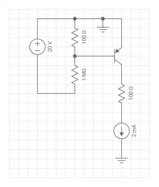
*Must be a transistor. A resistive divider doesn't span the minimum and maximum current. Also, a transistor worked very well on the positive side.