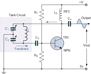
The circuit you have is essentially a common emitter amplifier feeding itself through an LC circuit. This circuit is slightly different due to the RFC in place of a collector resistor but in both cases the tank circuit works in the same way so to simplify matters lets look at this setup with a normal CE amplifier to see what's going on.
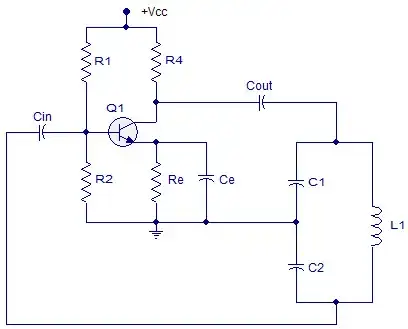
Image source: https://www.elprocus.com/colpitts-oscillator-circuit-working-and-applications/
We can then analyze it more easily by replacing it with a simplified amplifier model:
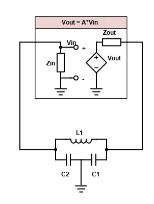
Here the amplifier is modeled in the box as a voltage controlled voltage source (VCVS) which has an output voltage \$V_{out}\$ proportional to the voltage across the amplifier's input impedance \$Z_{in}\$. (It's understood that the value of A is negative, i.e. the amplifier inverts the input signal). This output signal is then fed through the output impedance of the amplifier, \$Z_{out}\$, into the tank circuit, which then feeds back into the input of the amplifier.
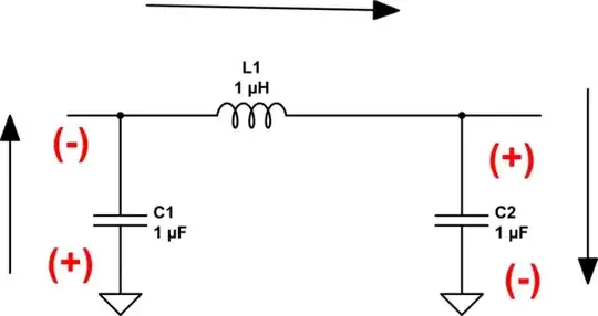
Forgetting that the voltage source is controlled for now, we can redraw the circuit more simply and analyze it to see how the phase of \$V_{in}\$ becomes shifted relative to \$V_{out}\$.
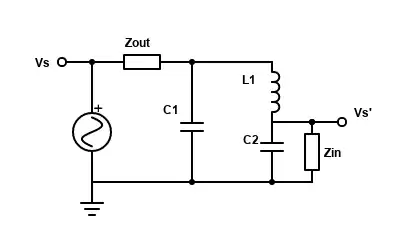
The output voltage of the amp is now modeled as a regular AC source and is labeled \$V_s\$, while the voltage at the point being connected to the input of the amp is labeled \$V_s'\$. (The voltages are re-labeled just so there's no confusion about inputs and outputs). The mesh current analysis to find \$V_s'\$ is somewhat lengthy so I won't go through it here, but it's a good exercise for anyone that wants to practice (find the current in the rightmost loop and multiply by \$Z_{in}\$ to get \$V_s'\$)
Taking the ratio of \$V_s'\$ to \$V_s\$ to find the gain, B, of the network, we get:
$$B = \frac{X_{C_1}X_{C_2}Z_{in}}{(Z_{out} + jX_{C_1})(Z_{in} + jX_{C_2})\left(\frac{X_{C_2}^2}{Z_{in} + jX_{C_2}} - \frac{X_{C_1}^2}{Z_{out} + jX_{C_1}} - j(X_{C_1} + X_{C_2} + X_{L_1})\right)}$$
One more approximation we can use to simplify this is that the input impedance is infinite, i.e. the amp draws no current into its input. This is something characteristic of an ideal amplifier as well as reasonable to approximate from a class A amplifier such as the one in the original circuit, so \$Z_{in} = \infty\$ is an OK assumption here. The other characteristic impedance of an ideal amplifier is that \$Z_{out} = 0\$, however this provides a 180 degree phase shift to every sufficiently large frequency, so this is actually not a desirable property and can't be assumed (this is why output impedance is deliberately added in the form of an RFC). In a common emitter amplifier, the output impedance approximately equal to the value of collector resistor and so it is purely real.
Substituting the infinite input impedance (taking the limit as \$Z_{in} \to \infty\$), the gain becomes:
$$B = \frac{X_{C_1}X_{C_2}}{(Z_{out} + jX_{C_1})\left( - \frac{X_{C_1}^2}{Z_{out} + jX_{C_1}} - j(X_{C_1} + X_{C_2} + X_{L_1})\right)}
\\ = \frac{X_{C_1}X_{C_2}}{-X_{C_1}^2 + (X_{C_1} - jZ_{out})(X_{C_1} + X_{C_2} + X_{L_1})}
\\ = \frac{X_{C_1}X_{C_2}}{X_{C_1}(X_{C_2} + X_{L_1}) - jZ_{out}(X_{C_1} + X_{C_2} + X_{L_1})}$$
The first thing to look at is what happens at the resonant frequency of the tank circuit. This is the frequency at which the reactances of the 2 branches are equal and opposite\$^1\$, i.e. \$X_{C_2} + X_{L_1} = -X_{C_1}\$, and has a value of \$f_r = \frac1{2\pi\sqrt{L_1\frac{C_1C_2}{C_1+C_2}}}\$. Under this condition the 2nd term of the denominator in the gain equation turns to 0 and we get that:
$$B = \frac{X_{C_1}X_{C_2}}{-X_{C_1}^2} = - \frac{X_{C_2}}{X_{C_1}} = -\frac{C_1}{C_2}$$
Capacitances are of course both positive real numbers so the gain is negative and we see that for the resonant frequency there is a phase shift of exactly\$^2\$ 180 degrees.
Intuitively, the emergence of this is quite simple. At the resonant frequency there is no net current flow in and out of the tank circuit because the branch impedances are equal and opposite and so the current flowing through them is equal and opposite (current flows back and forth -resonating- between the branches). This property is also indicated by its infinite equivalent impedance \$Z_{tank} = j\frac{X_{C_1}(X_{C_2} + X_{L_1})}{X_{C_1} + X_{C_2} + X_{L_1}} = \infty\$. Due to the lack of current flow there will be no drop across \$Z_{out}\$ and:
- The entire amplifier output voltage \$V_s\$ will be across the tank circuit
- With \$C_1\$ being a capacitor, the current through it will lead \$V_s\$ by 90 degrees
- Since the current through the \$C_1\$ is 180 degrees out of phase with the current in the other branch at resonance, the current through \$L_1\$ and \$C_2\$ will lag \$V_s\$ by 90 degrees.
- With \$C_2\$ being a capacitor, the voltage across it, AKA \$V_s'\$, will lag the current through it by 90 degrees
- In total, this results in the voltage across \$C_2\$, \$V_s'\$ to lag \$V_s\$ by 180 degrees.
To see what happens at other frequencies we can look at the gain and phase plotted on Desmos. Here the frequency is along the x axis with a logarithmic scale. I'll do my best to explain the trends:
At vanishingly small frequencies, the capacitors are for the most part open circuits and so there is no current flow and no voltage drop across the output impedance. The signal is virtually connected straight from the output of the amp to the input, unattenuated and unshifted (|B| = 1, \$\phi = 0\$).
At less small frequencies, the capacitor reactance decreases and they start to allow current flow which causes more of the signal to drop across \$Z_{out}\$ and we see a steady decrease in gain. As the total impedance becomes mostly resistive the current becomes more in phase with \$V_s\$ and so \$V_s'\$ (the voltage across \$C_2\$ which always lags current by 90 degrees) has its phase approaching -90 degrees.
At the series resonant frequency of \$L_1\$ and \$C_2\$ when \$X_{C_2} + X_{L_1} = 0\$, \$B = -j\frac1{Z_{out}}\sqrt{\frac{L_1}{C_2}}\$ and so \$V_s'\$ lags \$V_s\$ by exactly 90 degrees
As frequency approaches the tank circuit resonant frequency the gain spikes and phase rapidly approaches -180 degrees, due to the conditions that were explained earlier.
Past the resonant frequency, the tank circuit impedance drops to virtually 0 again because \$C_1\$ is still basically a short and so \$V_s'\$ approaches 0. And because the \$L_1-C_2\$ branch is now inductive rather than capacitive, the phase rapidly approaches -270 degrees (equivalently 90 degrees) as well.
You can also see by switching the capacitors for inductors and the inductor for a capacitor (changing the reactance formulas on Desmos) that these trends are reversed for a Hartley oscillator.
Also, notice by changing \$Z_{out}\$ that at very small output resistance the gain becomes less frequency selective and at \$Z_{out}=0\$ the whole thing breaks.
Hope this helps
\$^1\$ Notice that in the "untapped" tank circuit where the capacitors are in series, the condition for resonance, \$X_{C_1} + X_{C_2} = -X_{L_1}\$, is mathematically the same as the "tapped" version and therefore has the same resonant frequency. However they are different circuits and you shouldn't mistake the center tap as a trivial change.
\$^2\$ This is only exact due to assuming infinite input impedance. With finite \$Z_{in}\$ the frequency which is shifted exactly 180 degrees (and therefore the frequency which has sustained oscillations) is slightly different to the tank circuit resonant frequency.


