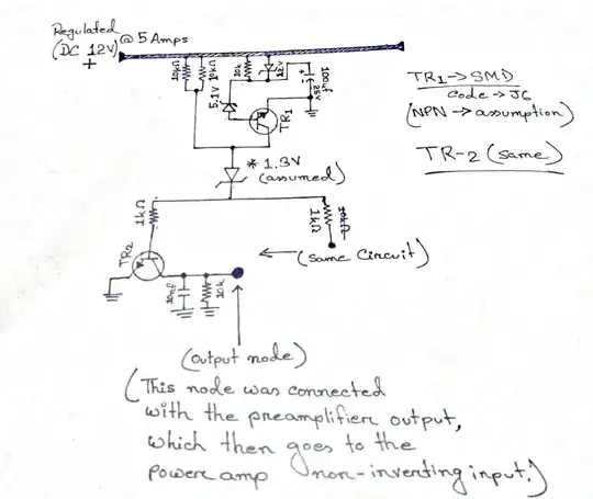
This is a circuit that I've found in my old amplifier board. Experts please help me identify this circuit and please describe how it works. I am sorry for my crude drawing, but this is what I found when drawing it from the circuit board. It was built using smd components so it was a bit difficult for me to find the exact match of the transistors. There might be some mistake in the circuit and it will be helpful if any of you take your time to rectify it for me. The output node was connected to the non-inverting input of the power amplifier along with the pre-amplifier output. My question is: what good does it bring to the power amp input? And how?
Asked
Active
Viewed 78 times
1
-
1I'd recommend finding a more descriptive title for your question. – Marcus Müller Jul 20 '19 at 18:05
1 Answers
1
My guess would be that it's supposed to be a power-on mute circuit — i.e., it keeps the preamp output grounded via TR2 for some time after power-on, in order to keep transients from passing through to the power amplifier.
However, the circuitry around TR1 doesn't look right at all. Try tracing it out again. Provide photographs (both sides of the PCB) if possible. It's possible that the transistors are MOSFETs.
Also, here are some tips about drawing schematics that make them easier for others to understand.
Dave Tweed
- 172,781
- 17
- 234
- 402
