A simple Ohmmeter would use a d'Arsonval movement meter as the basic measuring device. A good movement will include a mirror (curved to follow the sweep of the needle) behind it so that you can avoid parallax issues when reading the movement by eye. A good movement will also be rated as \$50\:\mu\text{A}\$ and perhaps \$2\:\text{k}\Omega\$ (implying \$100\:\text{mV}\$ to reach full-scale.) These are harder to find, these days, as they aren't so cheap to make (they are mechanical) and ICs and MCUs have greatly moved the cost/benefit away from d'Arsonval movements. But the TekPower TP7040, for example, appears to include such a movement and it's not expensive. So I recommend these to students. These also have advantages over digital meters. (See analog meter advantages.)
For a meter that supports several Ohmmeter ranges, it's not uncommon to find more than one voltage source being applied. Some of the old Simpson meters would include a \$1.5\:\text{V}\$ battery along with, say, a separate battery system composed of four \$1.5\:\text{V}\$ batteries in series to form a higher voltage supply for larger-valued resistor measurements. They also used switches to select the range, where different valued resistors might be placed in series with the meter movement. A separate variable resistor is used to calibrate the display for the zero-reading on the scale with the maximum resistance reading (\$\infty\:\Omega\$) being adjusted by a small screw on the d'Arsonval movement.
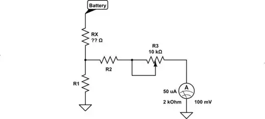
simulate this circuit – Schematic created using CircuitLab
The values of \$R_1\$ and \$R_2\$ are established by the switch setting and the design of the meter. It's also true that the applied voltage supply might also be different.
\$R_x\$ and \$R_1\$ form a voltage divider (which can be replaced with the Thevenin equivalent) that then feeds to \$R_2\$ and the calibration potentiometer, \$R_3\$, before reaching the meter movement. Together, this causes a small current which then moves the needle and allows the resistor value to be read from the movement's scale.
By changing \$R_1\$ and \$R_2\$ when you switch from one reading range to another, the divider changes and the resulting current through the meter is kept within its range and ability. Different scales are provided on the movement and you read your value off of the appropriate one to get the value.