3

Can someone please help me come up with a circuit with the following specification? I need to find out the difference of two voltages (can be done using an op-amp). Then, if the difference is negative, I want an output as -1V, if the difference is positive, I want +1V, and if the difference is zero, I want 0V.

I'm trying to build the backpropagation of a neural network using components like opamps etc. The weight update is given by w_o+ (a*(desired_output - observed output)* input to a neuron). Most of these can be done using multipliers and adders. However I'm not sure as to how can the part (desired output - observed output) be implemented. I know that it can either be 0, 1 or -1

Voltage Spike
  • 82,181
  • 41
  • 84
  • 220
  • 5
    Absolute speaking there is no "zero volts". So how close to zero should it be to be seen as zero? – Oldfart Jun 11 '19 at 18:34
  • As close as possible. In the sense, it should make very minute difference to the next part of my subcircuit – Vatsala Prasad Jun 11 '19 at 18:36
  • 4
    Use units. Do you need sensitivity down to 1mV, 1uV, 1nV....? – Chris Fernandez Jun 11 '19 at 18:37
  • And add in why you need this. What problem are you trying to solve? – Transistor Jun 11 '19 at 18:37
  • Well, I'm not really sure what you mean.. but I think instead of absolute 0 volts, even if it's in millivolts, that will do! – Vatsala Prasad Jun 11 '19 at 18:39
  • 7
    Aside from the requirement to detect 0 V as a special case, you're asking for a comparator. And you should probably re-think your requirement to detect the 0 V case. Or else use a window comparator to define what range of voltages around 0 V you consider to be "equal" to 0 V. – The Photon Jun 11 '19 at 18:40
  • 1
    @Vatsala: What we mean is that if you tell us what you are making then we may be able to help you avoid the strange requirement. There may be better ways to design the whole system. Add the details into your question using the edit link. Also define how many mV is acceptable. – Transistor Jun 11 '19 at 18:44
  • 1
    @Vatsala, what Chris means is, how big a difference between the signals do you want to have before you consider it as "not zero"? 1 V? 1 mV? 1 uV? 1 nV? Remember that all analog signals contain noise, so having two signals be exactly equal will only happen as a transitory phenomenon between $V_a<V_b$ and $V_a>V_b$. – The Photon Jun 11 '19 at 18:44
  • I'm trying to build the backpropagation of a neural network using components like opamps etc. So the weight update is given by w_o+ (a(desired_output - observed output) input to a neuron). So most of these can be done using multipliers and adders. However I'm not sure as to how can the part (desired output - observed output) be implemented. I know that it can either be 0, 1 or -1 – Vatsala Prasad Jun 11 '19 at 18:45
  • Are desired_output and observed_output digital values (having only discreet values possible) or analog values (they could be any value between two limits)? If the inputs are analog, why do you want to limit the output of your circuit ($a(V_a-V_b)$) to discreet values of -1, 0, and 1? – The Photon Jun 11 '19 at 18:51
  • In general terms of neural networks, they are digital values. However, bringing them down to a circuit is proving to be tricky. Also, since opamps (which I need for multiplication, addition etc) have a limit to the output value they can provide, I thought maybe I'll work with the digital values as voltages. – Vatsala Prasad Jun 11 '19 at 18:57
  • By this I mean, if I want a digital 1, I use 1V. If I want a -1, I use -1V, or if I want 0.3, I'll use 0.3V – Vatsala Prasad Jun 11 '19 at 18:58
  • I wonder if you might be able to do away with the zero case. The weights would jiggle around the target value but if the learning rate is small it may not be too detrimental. You could actually simulate that before committing to a circuit. – DamienD May 04 '21 at 18:14

3 Answers3

1

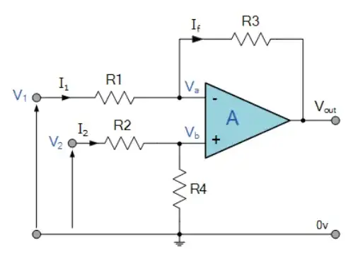
The way to find differences between two voltages in the analog domain is with a differential amplifier.

enter image description here
Source: https://www.electronics-tutorials.ws/opamp/opamp_5.html

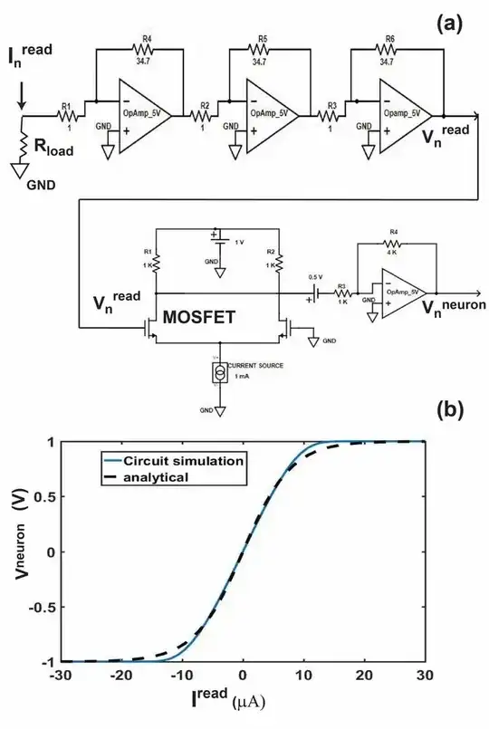
There are plenty of other ways to mimic a neuron, however. If you want one with the traditional sigmoid output -1 to 1 then this circuit might be most valuable.

enter image description here
Source: https://www.researchgate.net/publication/329207364_On-chip_learning_for_domain_wall_synapse_based_Fully_Connected_Neural_Network/figures?lo=1

Voltage Spike
  • 82,181
  • 41
  • 84
  • 220
1

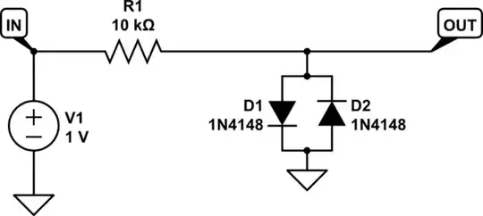
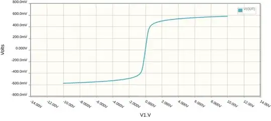
You can get a rough sigmoid-like response with a pair of diodes and a resistor:

schematic

simulate this circuit – Schematic created using CircuitLab

enter image description here

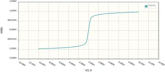
The output here isn't ±1V, and its impedance is probably too high to drive the input of some subsequent differential amplifier, but both of these problems can be solved with a non-inverting amplifier stage:

schematic

simulate this circuit

enter image description here

Simon Fitch
  • 34,939
  • 2
  • 17
  • 105
0

This is a two-part problem. The first one is easy: How to get the difference between two input voltages: Use a instrumentation amplifier. As you did not specify what the common mode (i.e. average voltage of the input voltages) does, I would recommend to go for the 3-amp instrumentation amplifier. There are fully integrated versions available from e.g. Analog and Texas Instruments. I strongly recommend to use one of these, if you are building discrete electronics. It is not easy to design an instrumentation amplifier correctly to work under all conditions, be fast enough and still have reasonable noise performance.

The second part of the problem is how to decide whether you are positive, zero or negative. If the decision would only be positive or negative, then a single comparator would do. But you require two comparisons/comparators. This will cause problems as zero volts is an infinitesimally small interval, which cannot be detected with any physical circuit. Thus you have to stretch the zero to become an interval large enough such that the comparators, with their offset voltage, drift and noise, etc, will go from "negative", "zero", to "positive" in distinct steps and never output "zero and negative" or even worse "positive and negative." Please keep in mind that you will need a tiny bit of hysteresis for the comparators to work properly, which will add to the width of "zero", otherwise you might get oscillations. There are some specialized two-comparator chips that are meant for range checking (eg. LT6700), but you will have to read the datasheet to make sure they work for your kind of application.
Attila Kinali
  • 1,226
  • 6
  • 12