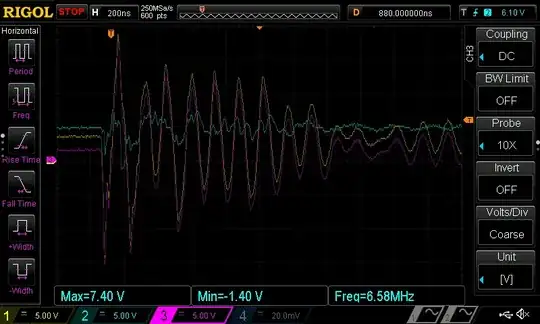
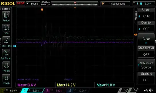
In the second scope shot, I'm not sure the chip's output isn't switching.
Most likely what you are measuring is EMI picked up by the scope probe cables themselves, not the output of your chip.
Instead of probing just the chip's output, also probe its GND pin right at the chip. This trace should display a nice, flat zero volts. If it does not, and it is picking up as much noise as the other traces, then your measurement setup is the problem.
You can only proceed to probing the chip's output once your setup properly measures 0V as 0V...
EDIT:
After all the probe was 1 meter away from the spark. Anyway, where do I connect the probe ground (alligator) when probing ground?
The probe's ground wire and alligator clip make a loop antenna which will pick up lots of noise from the ESD discharge. Try closing the ground alligator clip on the tip of the probe, just let it sit there probing nothing at all, and discharge your zapper at the usual distance. I bet you'll get a strong signal on your scope.
Also, as drtechno says, there is a ground loop between your probe, your scope (which is earthed) and through the power supply you use for your experiments, and finally to your board. Also a significant proportion of your spark's current will go through the scope probe's GND wire, since it has to go through somewhere to go back to Earth (or to your zapper). This will add lots of noise to your measurements.
In order to correct this, you either need a proper differential probe (best solution, but expensive) or you can hack it by using batteries to power your board, which kinda breaks the ground loop... although some current will still flow through the shield of the scope cable (that depends on how your zapper works, if it's like a stun gun then current won't loop back to Earth though).
Anyway. The best solution would be not to use a scope, for example if you have a microcontroller or other programmable device on the receiving board, you can program it to check if it detects a change in output from your chip or not.
Failing that, I'd solder a coax to the board, slip a big ferrite core on it, and plug that into the scope with a BNC, with the cable's shield soldered directly to the ground plane, and a 50R as source termination. First connect your 50R "probe" to the ground plane too, and run the experiment, try to guesstimate how much noise you get instead of a flat "0V". After this you solder the 50R resistor to the signal you want to probe, and remember that if you observe the same amount of noise as before, it is a measurement artifact. Only if you observe a lot more noise, then you can conclude that something's happening... That's a hack, but you should at least be able to see if the chip's output changes level or not.


