0

If the CMMR of a differential amplifier is given as 100dB at 50Hz in its datasheet, this CMRR value assumes the applied voltages wrt to common ground are equal. However in practice, if the line and source coupled to the amplifier are not perfectly balanced this CMRR will degrade.

For instance, Figure 1 below depicts a perfectly balanced case; and Figure 2 is an example of an unbalanced case due to R2 being different than R1.

enter image description here

In Figure 1 above since there is a perfect balance, I can use the datasheet's CMRR value. But how can we quantify the new degraded overall CMRR(CMRR') due to line imbalance in Figure 2?

Niteesh Shanbog
  • 711
  • 7
  • 21
user16307
  • 12,049
  • 52
  • 184
  • 320

2 Answers2

1

To calculate the system CMRR, you must evaluate the common mode to differential mode conversion that is occurring due to the mismatch of the + and - paths.

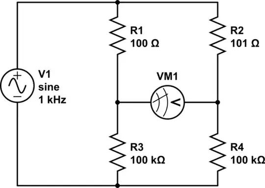
The signal amplitude at the output of each single ended half circuit is the impedance divider of the corresponding R and C.

The reactance is X1 = X2 = 1 / (2*pi*50 Hz * 10 nF) = 354 kOhm.

We can then compute the voltage divider at V+ and V-.

V+ = Vcm * X1 / (X1 + R1) = Vcm * 0.9984

V- = Vcm * X2 / (X2 + R2) = Vcm * 0.9968

deltaV = V+ - V- = Vcm * (0.9984 - 0.9968)

To compute the CMRR, compute 20*log10(A_dm / A_cm)

CMRR = 20 log10 (1 / (0.9984 - 0.9968)) = 56 dB

For the differential gain, I'm assuming that the input resistance is large enough compared to 500 ohm that that input resistance voltage divider is approximately 1. If that's not true, you can refine the A_dm calculation.

This shows the importance of having well matched inputs when using differential amplifiers. This is especially true if external components are added to filter the incoming signal. You'll want to get the best tolerances you can get to avoid the common mode to differential mode conversion. Traces / cables should be matched to minimize the differences in source impedance and parasitics.

I'll mention a few other topics related to maximizing system CMRR. Keep inputs balanced and have low component tolerances as discussed above. This is about minimizing the mechanism by which common mode is converted to differential mode.

The next idea is to minimize the amplitude of the common mode signal. Your Vcm is presumably due to unwanted power line hum (50 Hz) coupling into the system. Isolating the circuit from earth ground will reduce the coupled power line current that can flow. If the interference is capacitively coupling into the system, you can look into shielding the input cables / traces. This provides a low impedance node for the interferer to couple to, reducing the effects on the signal. Twisted pairs for cables minimize loop area, which can reduce inductive coupling to the signal.

Additionally, there are architectures such as the Right Leg Drive (RLD) in ECG circuits where the common mode is sensed and an inverted current is driven back to the source to cancel out the common mode current. This is an effective way to improve the system CMRR. This may or may not be possible depending on your application.

Mike
  • 1,051
  • 5
  • 8
  • 1
    You never used 100dB which is the CMRR of the amplifier itself at 50Hz in datasheet,. Do you take the CMRR infinity? if so please consider it as 100dB not infinity. – user16307 Apr 12 '19 at 03:09
  • 1
    At 56dB due to component mismatch, the 100dB of the OpAmp is ignorable. – analogsystemsrf Apr 12 '19 at 03:14
  • 1
    @analogsystemsrf I want to understand the logic here. What if the diff amps CMRR were 10dB instead of 100dB? What would be the overall CMRR? I mean 100dB neglected but if not neglected how would it add up to 56dB? – user16307 Apr 12 '19 at 13:20
  • There is 34dB of difference and 34dB is 50 times in linear terms, so it would change the result by half of fuck all. Were the amps CMRR 10db then there would be 46dB of difference, a factor of 200, so again a change of half of fuck all. dB scales are funny like that, once you have more then about 10dB or so of difference one of the numbers starts to become rapidly unimportant to the result. – Dan Mills Apr 12 '19 at 14:39
  • @Mike Is your voltage divider equations correct? Wouldnt the denominators be sqrt(R^2+X^2) http://www.iamtechnical.com/rc-element-frequency-dependent-voltage-divider – user16307 Apr 12 '19 at 18:42
  • Yea, 44 which changes the numbers slightly, I appear to have forgotten how to subtract. Basically without knowing the common mode input impedance you can only figure the effect of the lowpass filters formed by the caps but have no idea if the difference amplifier itself is going to be a limiting factor. – Dan Mills Apr 12 '19 at 20:10
  • @Mike Also the amplitudes are V+ and V- in your answer. But they are not in phase. You cannot just subtract them algebraically to find deltaV. Am I wrong? Please someone explain this. – user16307 Apr 12 '19 at 22:03
0

To figure this you need to know the common mode input impedance of the amplifier.

Basically the approach is to view the thing as a Wheatstone bridge with the two source impedances as the upper arms and half the common mode impedance as the lower.

schematic

simulate this circuit – Schematic created using CircuitLab

Here for example we have a 1 ohm imbalance into a 200k common mode impedance. It can trivially be solved as a pair of potential dividers, and is instructive to solve for a few different common mode impedances.

The amplifier CMRR will be given under some specified conditions, and it really, really mean them...

If you know the common mode impedance and the conditions under which the measurement of CMRR was made you can back track to the error in the two resistors at the bottom of the bridge, generally however you will find that the CMRR of the naked amp is either so much better then your complete circuit that it can be ignored or so much worse then your thing does in theory that it absolutely dominates.

I should probably give a mention to Bill Witlocks brilliant bootstrapped common mode circuit licensed to THAT Corp, it really is quite clever and works brilliantly with real world sources, well worth tracking down the datasheets for those chips.

Dan Mills
  • 17,516
  • 1
  • 20
  • 38
  • The datasheets only provide input impedance. How can I know/derive the common mode impedance? – user16307 Apr 12 '19 at 18:27
  • Sigh, datasheets without actual data, very annoying.... If it is a part with the common mode impedance set by on chip resistors then you can just read it off, if not then your options are basically measure it or take a WAG. – Dan Mills Apr 12 '19 at 20:03
  • I found one shows both https://www.analog.com/media/en/technical-documentation/data-sheets/6362fa.pdf Can you model this as resistors? I would be very glad. It says CM input resistance is 14Meg and diff input resistance is 14k. How can we model this as a resistive network similar as in your answer. Would be great if you provide a diagram as in your answer. – user16307 Apr 12 '19 at 20:10