2

enter image description here

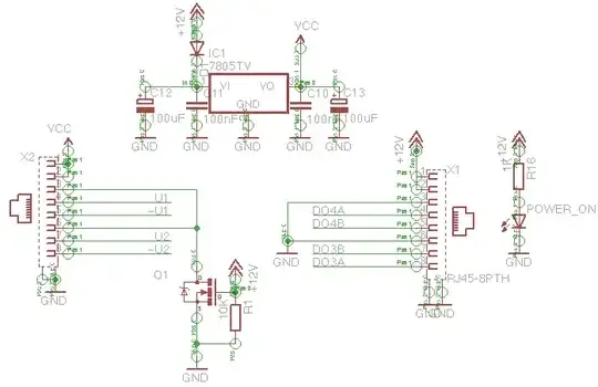
I'm building an adapter for rotary encoder that reads input of encoder and sends pulses by RS485. I'm using two RJ-45 connectors to provide power both for adapter and encoder. Both connectors have the same pinout. The right side connector receives 12V, theres linear regulator on board that powers RS485 transmitter/receiver chips and encoder.

I want to make some protection mechanism that would prevent failure when user connects 12V cable to output (left side) connector. Indication LED about wrong connection would be bonus.

All I was able to come up is a mosfet Q1 that has it's gate tied to +12V and 5V zener diode in series with resistor and "wrong connection" led.

Could someone advice me on more elegant/better way to do it?

House
  • 103
  • 3
miceuz
  • 5,561
  • 3
  • 40
  • 51
  • o yeah, i forgot to put a pulldown resistor at the gate of Q1 – miceuz Oct 08 '12 at 15:46
  • I'm not sure I understand the function of Q1. It looks like it's trying to connect the case ground and/or cable shield to the circuit ground, when 12 V is applied. – The Photon Oct 08 '12 at 16:34
  • oh! the schematics is wrong, sorry, i'll fix it in a minute – miceuz Oct 08 '12 at 17:34
  • what kind of load is on IC1 during normal operation? Also, is the regulator the only thing being damaged? – Analog Arsonist Oct 08 '12 at 22:05
  • @AnalogArsonist IC1 will have to deliver 300mA max. There are two other chips - quad RS485 receiver and quad RS485 transmitter. – miceuz Oct 09 '12 at 07:39

4 Answers4

10

It's bad practice to use the same type of connector in an application for different purposes, especially if plugging into the wrong connector can have adverse consequences. Using different connectors for different purposes is the best option.

vicatcu
  • 22,695
  • 14
  • 81
  • 156
5

Why not use a crowbar on VCC? The zener diode activates the SCR which is then like having a short across VCC and GND. It'll keep your circuit protected. If your power supply can't handle it you can always add a fuse.

enter image description here

Here's a link to a page about them http://axotron.se/index_en.php?page=26 We used this one time when we had software people who were always plugging 48V supplies into our 5V eval boards! We didn't control the connector barrels either so instead we used a crow bar plus a tiny fuse with a mechanical arm. Whenever someone plugged the wrong voltage in the crow bar would activate, blow the fuse, and the little arm would flick up and activate a warning led. We called it the FU circuit for obvious reasons ;)

Some Hardware Guy
  • 15,895
  • 1
  • 31
  • 44
3

You're MOSFET doesn't seem to be doing anything useful. Is it connected to the shield pins of the RJ45? I would just get rid of it.

You really need the blocking diode on the output side of the 7805, not the input side. 78xx-series regulators really do not like to be back-driven. To compensate for the diode's forward voltage drop in normal operation, you could put a similar diode in series with the 7805's ground pin.

That, plus your "wrong connection indicator" circuit, should be all you need.

Dave Tweed
  • 172,781
  • 17
  • 234
  • 402
0

To complement Dave Tweed's response, since he has multiple chips on the board they would also need to be protected. If it was just the regulator then he's only need two diodes. I think this would work. What do you think?

OV protection

Analog Arsonist
  • 957
  • 5
  • 10