0

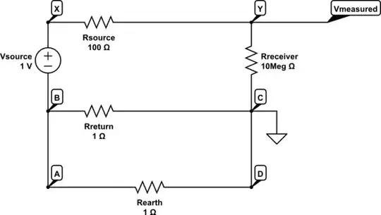
Below is a single ended system where the source and and the receiver are both earth grounded forming a ground loop through the earth which has a resistance of Rearth = 1 Ohm.

schematic

simulate this circuit – Schematic created using CircuitLab

As shown above, the output impedance of the source Rsource is 100 Ohm and the resistance of the return wire Rreturn is 1 Ohm.

I need to modify that circuit to model and simulate a 50Hz ground loop and see the effect of it on Vmeasured. I named the nodes as A, B, C, D, X and Y.

Will a ground loop current in such case loop through only A B C and D? Or will it also loop through A X Y and D?

Most importantly what kind of source and where I should add a source to model the ground loop. If possible, a modification on my circuit would help a lot.

cm64
  • 2,139
  • 1
  • 19
  • 46
  • A ground loop current will only flow when there is a ground loop and different ground potentials. There are none in your circuit therefore your question about ground loop current cannot be answered because there is no ground loop. – Andy aka Dec 13 '18 at 12:19
  • I know, that's why I need someone to correct this circuit by adding a 50Hz source(current or voltage). That is what I was asking about. Where to place a source that would model such ground loop I mean. I actually meant that in my question maybe it wasn't clear. I want to have a ground loop model but I dont know where to place the source for the ground loop current. Plus I dont know which nodes it would flow through. I made it in CircuitLab so the circuit is modifiable. If you can show me on it I would be very glad. – cm64 Dec 13 '18 at 12:29
  • That is like common mode voltage model. But they show the current pass through only shield not the signal wire thats a bit confusing.According to that model they show current pass only through shield. It is still not clear in my case(If there is such ground loop) would the current loop through only A B C and D? Or will it also loop through A X Y and D? – cm64 Dec 13 '18 at 12:45
  • We're in kind of a chicken or egg situation. You propose an egg and I suggest it might turn into a chicken and you prefer a duck shape. Try using words because clearly I'm misinterpreting what you want based on a circuit you are unsure of. – Andy aka Dec 13 '18 at 12:55
  • Okay let me ask this way: In your link here http://www.ni.com/cms/images/devzone/tut/a/af64be30617.gif, the ground loop current is shown flowing only through the shield. But they made it like a common mode voltage noise. In that case part of the earth ground current should flow through the signal line and between the non inverting and inverting input back to the ground. But they show it like the ground loop current flows only through the shield. What is the current's path or paths ? (Shield has some resistance I assume) – cm64 Dec 13 '18 at 13:01
  • The differential amplifier shown has high impedance to ground and therefore there is negligible current flow through the inner wires. If you want to apply equal value resistors at the receiving end to ground that would force current to flow. – Andy aka Dec 13 '18 at 13:08
  • I see Here at page 7 https://www.acromag.com/sites/default/files/The%20Importance%20of%20Isolation_1.pdf also they show this current as if it is flowing ONLY through the shiled or ground not through the signal wire. That was confusing me. So the answer is it is negligible on signal wire because of high impedance seen. Thanks. – cm64 Dec 13 '18 at 13:09
  • Thats why I was looking for another model because I thought it is only induced in that loop. – cm64 Dec 13 '18 at 13:09

1 Answers1

0

Ok, you clearly showed some effort and so I give you my 50 cent.

I suppose to consider only nodes ABCD as ground loop, because BCXY might typically be two wires in a cable connecting two devices. So this loop is usually small in area compared to the „classy” ground loop of the two earthed devices. (And yes, size matters in real world :)

Also BCXY is not a ground loop by definition.

A ground loop is always susceptible to time variant magnetic fields, which induce a voltage V in the loop (principle of electrical motor or generator). So you should insert a 50Hz AC voltage source in your model with some amplitude V. The question is if this V source should be modeled between AB or CD?

Please share your simulation results with us.

Stefan Wyss
  • 7,396
  • 1
  • 12
  • 24
  • That's very interesting. So that might be the reason they show it flowing through ONLY A B C D. So the voltage is induced by Faraday's law? But how can I model it regarding my circuit in question? How to place a type of source in my circuit that makes the earth current flow ONLY through A B C D? – cm64 Dec 14 '18 at 09:35
  • The current does not flow only through ABCD. But this loop is the reason for induction. So you should place an AC voltage source into that loop. – Stefan Wyss Dec 14 '18 at 10:18