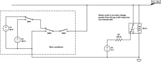
I have a wire that either floats - that's when I want to pull it up to 5V - or it may see up/down to +/-60V applied to it - and that's when I really don't want it to be connected to the 5V rail. Problem is that I can't figure out how to make a switch that will stay off when large voltages are applied to the wire. There are all these different combinations of voltages that can be applied to these wires - I'm only showing the extreme cases in the diagram.
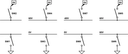
simulate this circuit – Schematic created using CircuitLab
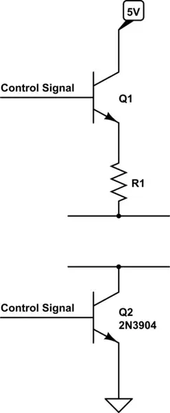
I want the switch to be closed only when the wire is floating (leftmost case on the diagram) and open in all the other cases. All my attempts were along the lines of connecting a BJT between the 5V rail and the wires - but all of that fails when the wire goes negative and the transistor is in the reverse active region.
I'm just curious at this point if this can even be done with discrete components, but if there's an IC that can do what I want that's fine by me. Thank you and I really appreciate all the help and advice.
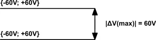
Edit 1: These two wires are inputs to a differential amplifier whose output is fed to an ADC. Input voltages range from -60V to +60V, but the two wires are never more than 60V apart. That means the top wire can't be at 60V and the bottom wire at -60V.
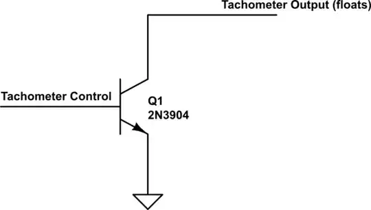
Sometimes the input is "dry" in a sense that it needs a connection to the power rails to produce a meaningful input. For example, the output of an open collector tachometer without a pull up will "float".
5V is a power rail that powers a lot of things in the circuit - that's why I want to protect it as much as possible. Also, +/-60V signal is an input to the op-amp and I'm worried putting a very large resistor will affect the accuracy of the measurements.
Edit 2: Can the following circuit possibly work? I ran a sim and it checks out.
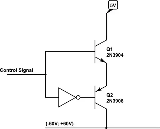