0

I'm really sorry to open some series of questions but since the issue is complicated I decided to open a separate question for a particular thing for not creating confusion:

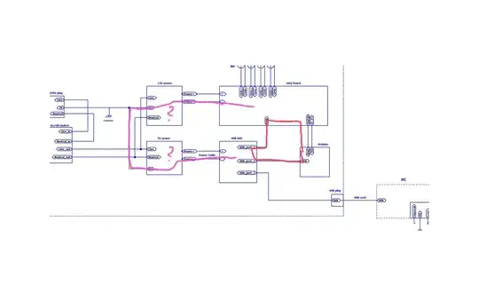
There is the red loop in below diagram which might be causing the EMI pickup I was told here. And then there is a second loop across the power supplies and the earth GND, usually is capacitively coupled.

enter image description here

It seems my main issue is the red loop. The long wires and the loop I guess pick up EMI.

But how can I physically star ground and minimize that area of the red loop or eliminate the loop? Or without any stargrounding is there a possible way to elimiate such spike only at node X. Here is another illustration where blue lines are showing grounds:

enter image description here

How can I filter the spike like noise due to EMI at the DAQ input node X? Are there ways worth to try? The spike occurs at all supply outputs but it is only an issue if it appears at node X in my case because of a software thing not hardware upset. Would a filter and an optocoupler be worth to try?
user1245
  • 4,125
  • 4
  • 38
  • 95

1 Answers1

1

There is no simple way to break that loop completely without actual isolation, but if the induced interference is of high-enough frequency you might have an easy work-around.

Get a ferrite core with considerably high-frequency losses, and loop one of your USB cables through it several times. That creates a common-mode lossy choke that would present a high-impedance to your aggressor signal while letting USB flow through unimpeded. You can do the same to the other USB cable.

There are ferrites designed for this purpose, but these are intended for low-level emissions not for high-magnitude aggressors, so their impedance might not be enough.

Edgar Brown
  • 8,426
  • 2
  • 18
  • 54
  • I see, you also mentioned actual isolation. Do you mean something like an opto isolator? – user1245 Dec 03 '18 at 21:36
  • Do you mean this type of ferrite rings? https://uk.rs-online.com/web/p/ferrite-rings/7880226/ – user1245 Dec 03 '18 at 21:45
  • @user164567 opto-isolation is a common alternative, but there are many ways to isolate digital signals. And yes, those types of ferrites, make sure to be able to get a few turns of the cable through it. I would also look for an assortment of common cord cores such as this one (https://katalog.we-online.de/pbs/datasheet/74272733.pdf) as if you can get away with just one or two turns this makes for a much cleaner-looking installation. They sell all of these things in kits. – Edgar Brown Dec 03 '18 at 21:54
  • Thanks a lot. One last question about this. If you look at my drawing, and if I interface an optocoupler between the Arduino and the node X I have to use a separate power supply for the opto output. That is fine but I will not be able to locate the power supply close to the point X(signal input). I mean after the optocoupler output there will be a two wire cable around 100cm long upto the point X. In that case should I use an STP cable or/and should I still consider toroidal ferrite cores around that cable? If I could not articulate well what I mean I can also draw thanks. – user1245 Dec 03 '18 at 22:13
  • If the supply for your opto is not at the receiving board, you are likely to introduce a new ground loop. That defeats the purpose. – Edgar Brown Dec 03 '18 at 22:17
  • I see the DAQ is a bit high 100cm above and Im not sure it has 5V supply built in. :( – user1245 Dec 03 '18 at 22:28