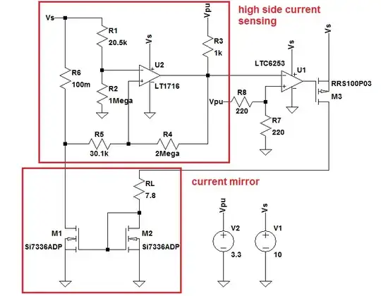
This circuit mainly consists of a high side current sensing circuit, a current mirror, an op amp, U1, working as a comparator, and a controlling PMOS, M3, to control the current through the load. Here's the schematic:
When the load current exceeds 1A the output of U2 becomes low and indicates an over current alarm. As soon as the current decreases to 0.5A the output changes to Vpu (=3.3V). The following diagram shows how the high side current sensing works:
The over current is denoted by IOC, and IREC is the recovery current. A 0.5A hysteresis margin is considered in this circuit but that doesn't matter for the purpose of this question.
So basically what I'm trying to do is shut down the load when it sinks >=1A and turn it on when it recovers back to safe operation mode, i.e. when it draws less than 0.5A.
For RL=7.8 ohms it draws ~900mA. So it hasn't yet exceeded the upper threshold and the output of U2 is still 3.3V and M3 on. But as I lower the load value to 7 ohms the simulation goes through apparently infinite iterations and never stops. I don't know why.. (I've tried ns, us, and ms stop times but they didn't work)
What happens is that as soon as IL hits the upper threshold, U2_out goes to 0V (actually 333mV) and U1 turns off M3, hence the load current momentarily drops to 0A - note that the propagation delay of U1 is a few milliseconds. Now with load current equals 0A the output of U2 changes to high again (surely delayed with a few ms), turning on M3 and RL continues to draw current. But as this current is still about 1A (consider the situation in the following paragraph), it makes U2_out low again and turns off M3. Then repeat..
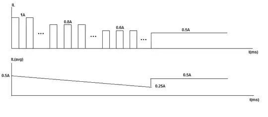
So by simulation I'm not able to prove whether or not this circuit works in practice. But let's consider a situation in which a DC motor (9V @ 0.5A) draws more than 1A due to overheating or excessive torque. Then I guess? upon drawing 1A it must stop, then work, then stop, then work, ... until it cools down and draws 0.5A. Of course, this happens very fast and the load might be too slow to respond to the changes. The following picture shows the (average) load current vs. time for when IL approaches 1A (again based on my guess):

The duty cycle is roughly 50%. If the pulsing current peaks at I amperes, the average current the load draws will be IL(avg)=0.5*I. As the load current decreases due to cooling, so does I. In other words, the load receives on average 0.5A all the way to 0.25A. Then it immediately jumps to sinking 0.5A and stays there or increases.
Another situation might be a constant load with RL=7 ohms or less. It will draw 1A but have to switch back and force with a ~50% duty cycle. So the average current it draws will be 0.5*1=0.5A at all times. Not very useful thing..
So questions: Why did the simulation go through infinite iterations? And most importantly, am I right with my above analysis? I may be wrong though..
Thanks for the time!

