I stopped using BJTs for a while and now I can't figure out why this configuration does not give me a 12 V PWM at the gate of the MOSFET? I am only getting slightly more than my PWM voltage about 4.2 V.
I have tried resistors at the gate to limit current and different resistors at the PWM for some input impedance but nothing. If I am not mistaken, when the top transistor is on it should effectively close that "switch" and I should get my 12 V at the gate. Maybe I've spent too much time playing with MOSFETs and I have forgotten how BJTs work.
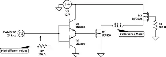
simulate this circuit – Schematic created using CircuitLab