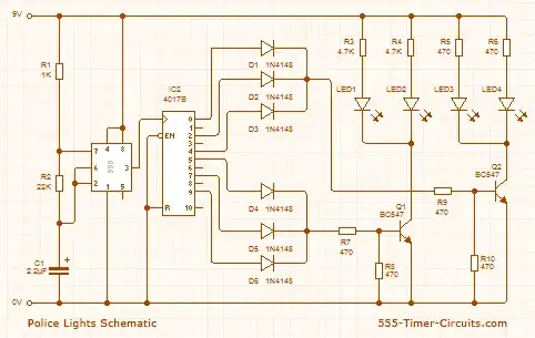
Is it safe to use a CMOS IC? For instance I'll be using a CD4017 in this circuit:
http://www.555-timer-circuits.com/police-lights.html
Will it still function correctly? Any further modifications needed?
Is it safe to use a CMOS IC? For instance I'll be using a CD4017 in this circuit:
http://www.555-timer-circuits.com/police-lights.html
Will it still function correctly? Any further modifications needed?
No, that's not guaranteed to work.

TTL low level outputs are no problem, but the high level may be as low as 2.7 V, and that's too low for a CMOS high level input.

Instead of a CD4000 series device I would use a function and pin compatible 74HCT4017. 74HC is High-speed CMOS (HCMOS), which is the technology most used today, the CD4000 CMOS is really outdated. 74HCT is the same, but with TTL compatible I/O (hence the "T").
Further reading
Logic signal voltage levels
Yes, using either a TTL or CMOS part should make no difference with this circuit. The levels appear to be compatible.
To clarify, at 5V the levels would not be compatible as Steven says, but at 9V things look a bit different - I'm working from the datasheets of the 555 and the CD4017. So:
The output high of the 555 appears to be Vcc - 2.5V at worst case (sinking 200mA). At 9V this equates to 9V - 2.5V = 6.5V.
The lowest input that will register as a high for the CD4017 at 9V is 0.7 * 9V = 6.3V.
So at worst case (which is unlikely in this circuit as the CMOS input does not load the 555 output) we have 0.2V margin.
For 5V, the result would be 2.5V for the 555 and 3.5V for the CD4017, not compatible - it's the 9V supply that makes the difference, as the TTL output is a fixed ~max 2.5V below the supply rail, whereas the CMOS input is a ratio, 0.7 * Vsupply. Having said all this, it's not ideal, and using an HCT part in these situations is less hassle as you know it "just works".
Notes on the Circuit
R3 and R4 are almost certainly a mistake, as this would only give the LEDs (9V - 2V) / 4.7kΩ = 1.5mA to operate with, and so will be pretty dim. These should be 470Ω like R5 and R6, to give ~15mA.
The 2V in the above calculation is the typical forward voltage (Vf) of a red LED, this will be slightly different for other colours so refer to the datasheet to calculate resistor for desired operating current. 470Ω will work okay for all types but there may be some difference in brightness between them (again, see datasheet)
The CD4017 output drivers are pretty weak, so I would remove R8 and R10 and change R7 and R9 to a higher value like 3.3kΩ. This should still provide plenty of base current for a half decent transistor.
The BC547 has a minimum current gain of 110, so for 30mA (2 LEDs at 15mA) only 30mA / 110 = 0.27mA is needed. Since gain drops in saturation picking a higher base current, say 3 times is a good idea) The 3.3kΩ will provide (9V - 1.4V) / 3.3kΩ = ~2mA, which should be plenty.
Looking into the datasheet of CD4017 I can wave a green flag. For minor projects you can implement an alternative if possible.Replacing some TTL with CMOS wont affect a lot until output and input levels are comparatively equal.
As stevenvh notes, the behavior of a CMOS input is generally not guaranteed if it is fed a voltage between 1.5 and 3.5 volts (assuming a 5-volt supply), and there's no guarantee a TTL output will exceed 2.7 volts. In practice, however, most CMOS inputs will regard a TTL high level as a high-level input. There are two main problems:
Using a 74HCT device rather than a 74HC device may alleviate the above-mentioned problems. On the other hand, 74HCT devices generally have more rigidly-specified power-supply requirements, and often require more current than 74HC devices. In practice, those issues aren't apt to matter since TTL devices will require 5 volts and draw a lot of current anyway, but they do mean that it's generally better to use non-HCT devices when not interfacing with TTL.