0

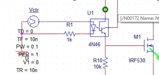
I want to learn how to size the series resistor for this optocoupler which has a high CTR.

I will use Arduino's 5V digital output pins for eight of this coupler so I really want to source necessary enough current from each pin.

enter image description here

What is the method to calculate the optimum like series resistor(R1 above) in this case?

user1245
  • 4,125
  • 4
  • 38
  • 95
  • Although I've no idea where those off-image wires go, it looks to me as though your 4N46 is struggling to be a high side switch with an NPN Darlington arrangement. Not so good. Take a look at the data sheet and find the test circuit examples there? Also, what is the highest frequency you hope to apply? – jonk Oct 26 '18 at 03:04
  • @jonk What is not so good you meant? I think pin 6 should be not connected for this arrangement thats why there is green circle indicator. It is to turn on or off a device. Not repetitive use. So frequency is less than 1Hz in normal conditions. – user1245 Oct 26 '18 at 08:37
  • @atomant. That is not correct. The base pin is too set the gain of the transistor by connecting resistor from base to emitter. 100K will give you a gain of about 100. 470K will give you a gain close to 500. –  Oct 26 '18 at 19:23
  • @Sparky256 see my other question https://electronics.stackexchange.com/q/402989/134429 they say pin 6 should be floating. What do you say??? – user1245 Oct 26 '18 at 20:06
  • Try reading the datasheet for a change. –  Oct 26 '18 at 21:20

1 Answers1

1

'IRLED' in this case means the infra-red LED inside the opto-coupler.

The IRLED drive current is Vin-1volt/R1. You subtract 1 volt from the source voltage to account for the IRLED Vdrop of 1.05 volts, then divide by R1.

In this case it should be 3.3V - 1 = 2.3V/1K = 2.4mA. That will drive most any opto-coupler.

There is no 'ideal' current except to try for minimum LED ON current x 2 or x 3. Whatever gives dependable results. That fact that it might have a maximum rating of 30mA is not what your looking for. Results for power conservation and heat control should be based on the IRLED minimum ON current that will saturate the output transistor fully ON-no more than that.
  • 3.3V will be 5V I will use 5V from Arduino pin out. So what is the goal to size the resisotr? To fit the current to 2.4mA? I dont understand.. – user1245 Oct 26 '18 at 08:37
  • I gave you the equation in my answer to solve R1 for any source voltage. It is very simple to use. –  Oct 26 '18 at 11:20
  • Ok thanks so I can set the current to LED ON current X 2. Is the LED ON current written in the datasheet? – user1245 Oct 26 '18 at 11:30
  • Yes, the datasheet supplies all those details. –  Oct 26 '18 at 19:17