Let's say I have a matrix of square 12.7 mm cells. Every cell is a connector to which an independent little piece ("little piece" is a building block) may be connected. Actually, it's a little puzzle/sandbox game (a hobby project) where you have to build a circuit out of small building blocks like wires, logic gates, sensors and so on.
Every little piece has 4 contacts connected to it: +5V, CLK, RST, GND. Originally I wanted to make 4 rings: the inner is RST, then CLK, then +5V, then GND.
I'm planning to make the little pieces as PCBs at some cheap prototyping website or just at home. Making a PCB for the connector board is an overkill and will be quite expensive. I could buy some perfboard on Aliexpress and solder everything but this would be too prototypish, IMO. On the other hand, connecting the 4 rings or similarly put pin sockets in some plastic container with holes is very complicated, so I decided to switch things up a bit.
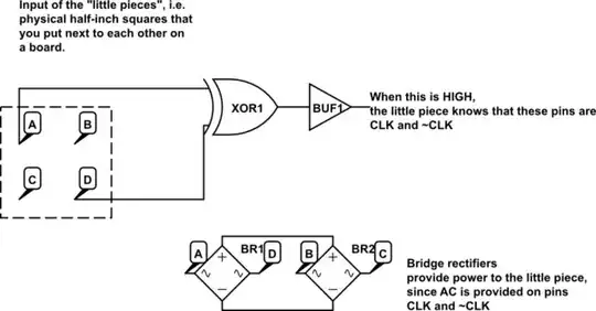
Now I have just 4 pins. Pins A, D are both =RST, and pins B and C always have different values: CLK and ~CLK. Therefore, the little pieces can go either way, and that's important. The little things would identify which two pins are complementary CLKs and which are RST using an XOR gate. The power is collected into a capacitor through a bridge rectifier in case both CLK and ~CLK go low or if the piece needs extra current.
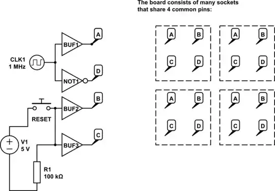
simulate this circuit – Schematic created using CircuitLab
This is the internals of a "little piece":
My questions are:
1) Are there easier ways to do this? Are there readily available sockets or designs for my purpose?
2) What obstacles and problems will I encounter actually designing everything (apart from size constraints, although I can make a little piece occupy several cells)?
3) How to choose the right R and C values for a given frequency?
 This-ish connectors might work as well if I applied some thought to the connections.
