I'm trying to make a high power UPS, I have a 13.6V PSU and an Inverter and a Lead acid battery.
Everything would be connected this way:
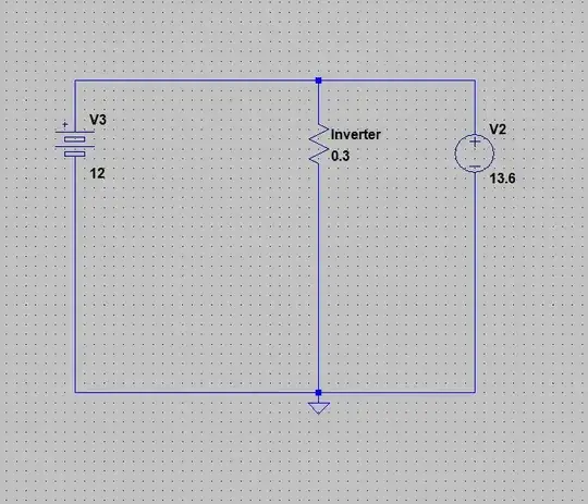
There's a problem with that circuit, if the battery is too discharged the initial charge current will be too high for it, so I need to limit the current while charging and not while discharging.
The simplest solution would be this:

But that solution isn't very efficient. So now the next thing that comes to my mind is using a mosfet as diode, like the reverse polarity protection circuits. I only have N channel fets, so the end result should be this:
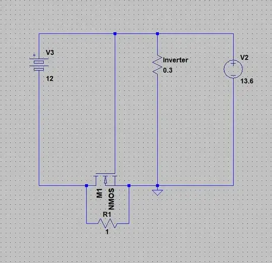
However according to LTspice that circuit doesn't work. As long as it is the default Nmos it does work, but if I try to replace it with with any Nmos in ltspice's catalog (Mosfets with a VGS above 20V), the MOSFET still conducts when it shouldn't. Why?
By the way, the MOSFET I want to use is an IRF3205.
There are several images that explain how to use an Nfet for reverse polarity protection. I have it according to those.
– Phoenix1 Jul 30 '18 at 04:01Rserparasitics into at least one of them). Also, you may wish to change the default NMOS with a readily available model, or at least with one of your own (or subcircuit, whatever works for you). – a concerned citizen Jul 30 '18 at 07:39I want the mosfet to be close when current is drawn from the battery to the Inverter, and to be open when the PSU is on. So that the charging current that goes to the battery is limited by the 1 ohm resistor.
– Phoenix1 Jul 30 '18 at 08:14When the PSU is off (power failure) current goes from the battery, thru the diode (and some thru the 1 resistor as well) to the inverter. Now since the diode is forward biased, the current from the battery isn't limited, however there's still the schottky diode voltage drop that adds inefficiency to the circuit.
The solution is to replace the diode with a low RDS on fet, however it allows current from the PSU to the battery when it shouldn't right?
– Phoenix1 Jul 30 '18 at 08:25