0

I want to have a light bulb as a daytime running light that is located next to the turn signal (blinker). Since that daylight running light is kind of bright (having a clear lens) I want it to turn off while the blinker is on (flashing) and MAYBE stay OFF for ~2+ seconds after the blinker is stopped.

What size and kind capacitor is needed to smooth out the signal from the blinker? (given that the capacitor has the time to charge while the blinker is on) The Blinker has less than a 1 sec frequency.

1994 BMW 840Ci is the vehicle if anyone wants or knows how to find more info.

Blinker - 12v 21W
Daytime Running Light - 12V 21W
NC Relay
NO Relay ACC - Accesories turned on

Any suggestions on how else this could be done, would be greatly appreciated.

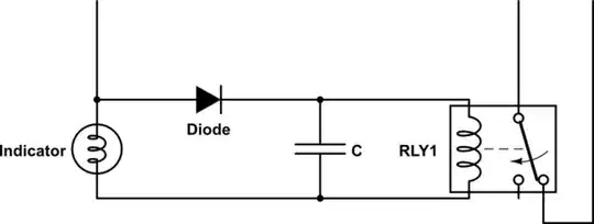
And here is a diagram with what I was thinking. I hope someone would make some sense of it. enter image description here

Best regards, Gio

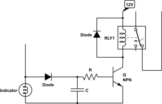
Thank you for the inputs, I have made a new schematic that makes sense to me right now. oh boy!

https://www.circuitlab.com/circuit/896vjn68c232/bmw-840ci-drl-schematic/

enter image description here

  • 1
    You may cause a problem by connecting any extra load to the blinker circuit. They ofen change speed if one of the lamps fail. – Finbarr Apr 02 '18 at 09:22

2 Answers2

0

The bottom part of your diagram will not work with the way you have placed the capacitor. Below you will find a better diagram of what might work. The 2 second delay greatly depends on amount of current the relay takes. You will likely need a big capacitor with this diagram.

schematic

simulate this circuit – Schematic created using CircuitLab

If you add an NPN transistor as amplifier you can use a much smaller capacitor. Also the load on the indicator driver is much lower thus your indicator circuit is very likely to work normal.

schematic

simulate this circuit

Both of these are principle diagrams. I am afraid for details we need to know more about the NO relay in your picture.

Oldfart
  • 14,380
  • 2
  • 16
  • 41
  • For the diagrams we need to know the resistance of the coil.Also if you use a relay which OPENS a switch when activated you can do the diagram with only one relay. – Oldfart Apr 03 '18 at 06:32
  • My new diagram https://www.circuitlab.com/circuit/896vjn68c232/bmw-840ci-drl-schematic/ – gio turbatu Apr 05 '18 at 05:44
0

I decided to give a second answer based on the new diagram you added.
First: There is a diode missing over your relay (Check my diagram). Use wikipedia with 'flyback diode' to know why that is essential.
Second: In your diagram the day time running light goes ON if your indicator goes on, not OFF. You should use the other contact of the relay.
Thirdly: (I have not broached this at all yet) There seems to be no way to switch the day time running light OFF. I assume you want the supply to come from after the ignition switch.
Forth: As I mentioned in the comments: you use a relay to switch another relay. If you really want to use two relays that is fine but you can do the circuit with only one relay.

I had a search for the typical coil resistance and found a figure of between 50 and 200 Ohms. Assuming the worst case (50 Ohm) your transistor must switch ~250mA. In a car there can be high voltage spikes (100V) so use a NPN with Vce=100V Ic=~1A. (TIP31C transistor or equivalent). For the timing I would try R = ~820Ohms, C = ~1000uF.

Oldfart
  • 14,380
  • 2
  • 16
  • 41