0

How to control a voltage using PWM out of a microcontroller that can handle a load consumes 20 Amp current..

Load is a heating coil that has a resistance of 0.21 Ohms, power supply 4.2 v Li-Ion battery, PWM 0 / 3.3 volts ..

Mohamed Sayed
  • 51
  • 1
  • 6

2 Answers2

3

I believe a simple logic level N-MOSFET will solve your problem.

  • Logic level means that the threshold voltage of the gate to source is less than 5 V, or 3.3 V, it's a sloppy term. It will be around low voltage logic, like a MCU.
  • N-MOSFET means that in order for the transistor to conduct, the gate of the N-MOSFET has to be above the threshold voltage from gate to source.

Here is a schematic for driving it, assuming the heater is purely resistive. If you are going to drive a motor or something else that is inductive in the future and think that this is a good schematic for that, then you need to put a diode in parallel with your motor. Otherwise the back-emf will probably destroy your circuit.

schematic

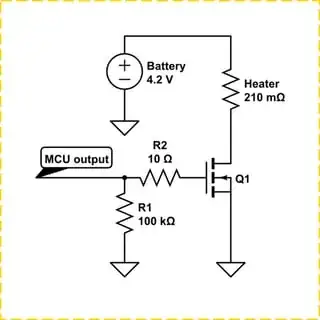
simulate this circuit – Schematic created using CircuitLab

The 100 kΩ pull down on the gate is there so if the MCU breaks or takes too long to start up when you connect the battery, or whatever, just the MCU is non-responsive. Then the gate to the MOSFET will be drawn down to source (0 V in this case) and turn the MOSFET off.

The 10 Ω gate resistor is to reduce the ringing of the gate, the ringing quickly opens and closes the gate and messes up the output. Without the ringing it will behave as you want. Ringing is, as far as I know, not something you want.

Now you should start looking for MOSFET's that can drive 20 A, but if you only look for those that are made for 20 A, then there's no margin for error. What if the heater has 200 mΩ? That's 21 A. Your MOSFET is conducting current it's not made for, things will start to heat up and if you're unlucky, melt down. So look for a MOSFET that can safely pass 30 or even 40 A.

If you got some MOSFET's rated for 10 A, then you can use 3 or 4 of them in parallel. Just connect their drains to drains, gates to gates and sources to sources.

A heater has a slow temperature change time, so the PWM can probably go as low as 1 Hz, meaning if you want a PWM with a duty cycle of 50%, then 500 ms on and 500 ms off would most likely suffice. I can't tell for sure because I don't know how your heater looks like. But you can also safely drive the heater with 1 kHz or 10 kHz or 100 kHz PWM.


Here is a link to digikey showing some viable MOSFET's that you can put in parallel. I first looked for MOSFET's for 40 A but saw that none of them had their lowest \$R_{DS(ON)}\$ when fed 3.3 V, so I looked for all MOSFET's that were fully on at less than 3.3 V and then looked for the MOSFET's able to conduct more than 4 A.

DMN1019USN-13 is a cheap one able to conduct 9.3 A continuously if the voltage at the gate is above 2.5 V. So just get 3 of these and put in parallel like I previously described and you will be set. The \$R_{}\$ for this MOSFET is 12 mΩ, with 3 of these in parallel it will be \$\frac{12\text{ mΩ}}{3}\$ = 4 mΩ.

So if the MOSFET is conducting, then the current will be \$\frac{4.2\text{ V}}{210\text{mΩ + } 4 \text{ mΩ}} = 19.626\text{ A}\$.

The power dissipated in the heater will be
\$P=A^2R=19.626^2×210\text{mΩ}\approx80.89 \text{ W}\$

And the power dissipated in the MOSFET's will be
\$P=A^2R=19.626^2×4\text{mΩ}\approx 1.54 \text{ W}\$

And it's 3 MOSFET's, so \$\frac{1.54 \text{ W}}{3} \approx 510 \text{ mW}\$ will be dissipated per MOSFET. I think you might want a heat sink, maybe even a small fan.

Each of the MOSFET's can according to their datasheet dissipate 680 mW at room temperature. So it should be fine... The error margin is 680-510=170 mW. Maybe a little bit too close for comfort. At 75 C° they can dissipate 400 mW. So if they are near the heater they might get warmer and not able to dissipate enough heat. So you might want to add one or two transistors more (very cheap), or add a heat sink and a fan (more expensive energy wise and money wise).

With...

  • 3 MOSFET's => 1.54 W dissipated in them, 510 mW per transistor.
  • 4 MOSFET's => 1.16 W dissipated in them, 291 mW per transistor. <400mW
  • 5 MOSFET's => 0.93 W dissipated in them, 187 mW per transistor
  • 6 MOSFET's => 0.78 W dissipated in them. 130 mW per transistor
  • 7 MOSFET's => 0.67 W dissipated in them. 96 mW per transistor
  • 8 MOSFET's => 0.59 W dissipated in them. 73 mW per transistor
Harry Svensson
  • 8,169
  • 3
  • 34
  • 53
  • Do mosfets get more conductive as they heat up or less conductive? – BeB00 Feb 18 '18 at 03:19
  • @BeB00 Less conductive. BJT get more conductive. - The heating gives negative feedback for the MOSFET and positive feedback for the BJT. So the MOSFET's will balance themselves automatically, unlike if there would've been BJT's instead. With BJT, one will get warmer and get even more warm and burn up, then the next.. the next.. until voilla, no more BJT's. – Harry Svensson Feb 18 '18 at 03:26
  • I just have another two questions please : 1- If I want to estimate the resistance of the coil by considering the coil resistance and the MOSFET resistance as a voltage divider that feed an op-amp, does the Rsd of the MOSFET changes or it would be constant ? 2- Is there any idea to measure the controlled voltage by the MOSFET electronically or programmatically by some equations ? – Mohamed Sayed Feb 18 '18 at 03:38
  • @MohamedSayed (1) The $R_{DS(ON)}$ changes with temperature, goes up as temperature goes up. The coil's temperature will most likely also go up as temperature go up. But you probably don't know if they go up by the same factor. I don't at least. So I would say no, you can't just measure the node between them, you need to add a shunt resistor in series with the heater to measure the current, and then measure the voltage at the node between the MOSFET and the heater. Then you got enough information to correctly calculate the resistance of the coil. – Harry Svensson Feb 18 '18 at 03:47
  • @MohamedSayed (2) It would be very similar to trying to calculate the amount of power your computer takes right now. There's too many unknown variables so your answer will most likely not be remotely close. If you're near the answer then you can call that luck. If you just want a horrible approximation, then make a horrible approximation, if you want the real deal, then measure it. - FYI, the voltage will move like a square wave, likewise will the current. The square wave for the voltage extreme points can be approximated to 0 V and 4.2 V, the average will be the duty cycle of the PWM × 4.2 V – Harry Svensson Feb 18 '18 at 03:52
  • @MohamedSayed If I were you, I would just get a heater sensor and use that for whatever I am doing. Because I assume you are going to heat something up. Rather than calculating the average voltage => average power, then you should just go straight to what you actually care about. The temperature. So put a LM20 nearby and you will be able to read the temperature in the range of -55 to 130 C°, or just use a thermocouple. It's up to how you are going to use your heater. -> I <- don't know. – Harry Svensson Feb 18 '18 at 03:57
  • So the RdsON changes won't effect the Total resistance of the shunt resistor and heater in series that much ? Just want to confirm that RsdON won't changer over voltage variation... I may rely to the datasheet of MOSFET for corrections in MCU code.. the second part please: how can I measure the voltage ? I tried to measure it directly at the heater node that is connected to the battery and the result was 4.2 v the voltage of the battery not the controlled voltage – Mohamed Sayed Feb 18 '18 at 03:58
  • @MohamedSayed The $R_{DS(ON)}$ will indirectly affect the resistance of the heater, by heating it up and therefor change it's resistance. - I am not 100% sure what you mean by voltage variation. - The voltage across the heater will be 4.2 V minus the node voltage between the MOSFET and the heater. So if the MOSFET is on and you measure 100 mV at that node, then the voltage across the heater is 4.1 V. - This will probably be my last comment, otherwise some moderator will come by and move all of the comments into a horrendous chat system because this is turning into a discussion. – Harry Svensson Feb 18 '18 at 04:03
  • 1
    Thanks to your above advices I successfully achieved my goal, a differential op-amp AD8268AR between heater to get the drop volt, and another one between shunt resistor to estimate the current both feeding ADC to calculate the resistance of the heater (heater R = heater drop volt /current).. and worked so fine, my last question Harry and I need your kind helping in a new thread, I will appreciate your reviewing, here you are : https://electronics.stackexchange.com/questions/357049/pwm-rise-and-fall-time-frequency-and-duty-cycle-setting-to-control-voltage-usin – Mohamed Sayed Feb 19 '18 at 08:11
0

"Logic Level" NFET will work. To limit self heating to <1/4W (oops too much brunch wadka) how about < 2W with heatsink \$R_{on}=W/I^2=2W/20A^2 =5 mΩ \$

https://cdn-shop.adafruit.com/datasheets/irlb8721pbf.pdf

Curve says 0.2V *20A =4W typ

StainlessSteelRat
  • 7,996
  • 2
  • 18
  • 34
Tony Stewart EE75
  • 1
  • 3
  • 54
  • 185