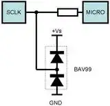
In the case you show the diodes act as clamping diodes to protect the input against too high or too low voltages. The top diode will clamp the input to +Vs + 0.7 V, the other one will clamp the input to -0.7 V. The small advantage is that they have a the anode of one diode in common with the cathode of the other.
Other double diodes, like the BAT54 are available in different configurations, so that there's always one for when you need two connected diodes:

Note that even the single BAT54 comes in a SOT23 package, so placement of two single diodes requires six pins to solder, versus three pins for the double diode. Soldering cost is calculated per pin, and for simple components may exceed the cost for the part itself. And it also saves board space. Apart from the series, common anode and common cathode arrangements there are also independent double diodes, like the BAS40-07, which again may be used to save board space and cost.
The BAV99 diode is also half of a bridge rectifier, and the BAV99s has two of them for making a bridge.
Apart from less signal routing through the common connection you can also use double diodes when they need to be well matched, since they're on the same die.