EDIT - on reflection, the circuit below (which I'll leave for reference) is probably best suited for use in circuits without a micro. AS mentioned in the other answers, unless you really can't afford the few uA, it doesn't really make sense not to use the micro to control the power toggle, as it uses less components and can be controlled accurately.
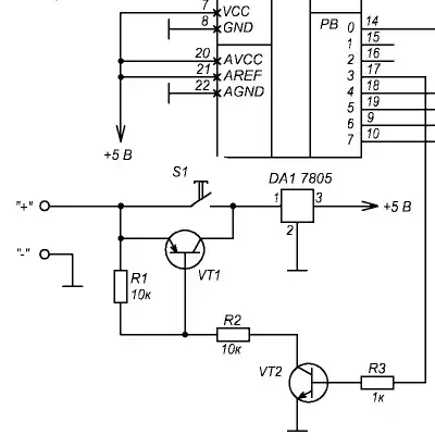
The simplest version can be something like a IOC (interrupt on change) input with pull up, with button to ground. The micro has power applied all the time, and controls a P-channel MOSFET (with pullup from gate to source) for the rest of the circuit. When it sleeps it lets the gate float to turn the circuit off.
Reference circuit:
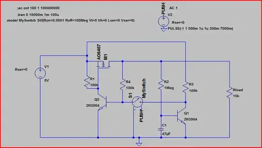
At first The P-MOSFET is off, so there is no base current at Q2, which is also off. Q1 is off, so Q1c is at 5V. The circuit is static.
When S1 (ignore the + and - nodes, they are there for SPICE triggering purposes) is pressed
the 5V at Q1c is connected to Q2 base, turning it on. This pulls the P-MOSFET gate to ground, turning it on as well.
R4 now sees 5V and when S1 is released, it provides Q2s base with the current needed to keep it open (and therefore the MOSFET on too) Q1 is also turned on when current through R2 charges C1 to ~600mV, at which point Q1c is <200mV (i.e. Q1 is turned on)
The circuit is now static again.
When S1 is pressed again, Q1 sinks the current from R4 (which is keeping Q2 on) turning Q2 off. R1 pulls the MOSFET base up to 5V and switches it off again.
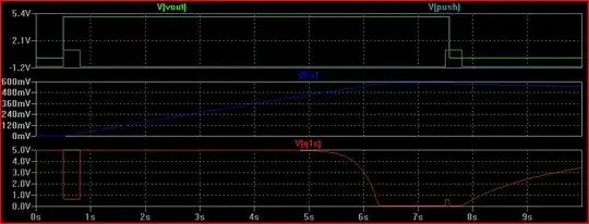
Here is the simulation (V(push) high represents when the button is pushed):
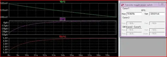
Also we can see after power off the current heads to zero (as C1 discharges and Q1 turns off) so the circuit consumes no power in the off state (the cursor for I(V1) is at 19.86s and measures 329nA):
The original circuit idea is not mine, it comes from Dave Jones over at EEVblog.