3

enter image description here

What is the purpose of the 1 microfarad capacitor in this circuit? The source webpage says:

Output of TSOP1738 oscillates at the rate of 38KHz, which is applied to clock pulse of 4017. So we have connected a 1uF capacitor across the output of the TSOP so that this 38KHz pulse train is counted as one clock pulse to the IC 4017.

However, I could not understand what this means:

So we have connected a 1uF capacitor across the output of the TSOP so that this 38KHz pulse train is counted as one clock pulse to the IC 4017.

The circuit does not state the voltage of the capacitor, but I bought and used a 1 microfarad 16 volts capacitor. How 1 microfarad capacitance and 16 volts rating of the capacitor affect this circuit? Is the capacitor really needed?

Source webpage (remote-controlled light switch): https://circuitdigest.com/electronic-circuits/remote-controlled-light-switch

UPDATE:

If I understand correctly, each pulse from a TV remote control for example produces a maximum of 6 volts at the output pin of TSOP1738 and charges are stored in the capacitor. But how does the capacitor know when to release the charges it holds to IC's pin 13? Does the capacitor wait for the burst of pulses to finish before releasing the charges to the IC's pin 13?

user1764381
  • 223
  • 4
  • 9
  • hm, it would act as a RC low pass of sorts with R1. Personally: find a better source. – Marcus Müller Nov 04 '17 at 19:01
  • This is a poor-man's IR switch. It toggles On-Off on any IR signal received. The 1µF cap, together with the 80kΩ pullup built into the TSOP1738 (see its datasheet!) forms a very rough timer circuit. 16V is okay. Without that cap, the counter would count any single pulse of the signal instead of the bursts, which would lead to a seemingly random On-Off switching. – Janka Nov 04 '17 at 19:02
  • Is it only me or is Q1 upside down ? – Mike Nov 04 '17 at 19:05
  • You are totally right, Mike. It's upside down. – Janka Nov 04 '17 at 19:06
  • @Janka, the datasheet is too advanced for me. Is there a beginner way to understand how that cap works and when are the charges stored in that 1 microfarad capacitor released? Thanks – user1764381 Nov 04 '17 at 19:34
  • Don't build this circuit - the supply voltage rating of the TSOP1738 is being violated. – Chris Stratton Nov 04 '17 at 20:12
  • @Mike that may be intentional to use the load Hfe side of the transistor. Really ugly circuit though. I`m guessing they used the huge capacitor so the thing needs to be operated by a long ~flash~ of the transmitter and so it is not tripped by say your TV remote. But who knows. – Trevor_G Nov 04 '17 at 20:27
  • i have made this circuit but there i am facing a problem that my circuit is automatically turning on and off without any command then can anyone tell me that why it is happening and how to solve it. – SANJEEV KUMAR RAJPUT Apr 19 '19 at 05:10
  • I really think the BC557 is connected the wrong way. An exactly similar tested design can be seen in the first diagram from this article. https://www.homemade-circuits.com/how-to-make-simple-infra-red-remote/ The capacitor is for creating stabilized clocks for the 4017 input – Swagatam Majumdar Apr 19 '19 at 05:46

2 Answers2

7

... the datasheet is too advanced for me. Is there a beginner way to understand ...

Sure. Let's do it in stages.

Modulated waveform

enter image description here

Figure 1. Infrared modulated and demodulated signals.

  • Remote control signals are transmitted as a series of pulses. If you look at the LED on your TV remote using your camera phone you can see the irregular flicker as you press the remote buttons. The remote control codes are sent at a relatively low speed of up to 1200 bits/s according to the datasheet.
  • Each pulse for one bit will, in turn, be made of a burst of high frequency pulses. The top of the datasheet shows that the chips are made in versions from 30 kHz to 40 kHz. Having rapidly changing levels like this helps the receiver discriminate between background infrared from other sources. Effectively the receiver is looking for a fast AC signal and ignores anything else.

enter image description here

Figure 2. The innards of the TSOP demodulator.

  • The TSOP chips make decoding the signals easy because they demodulate the output and restore the low frequency signal. See the output signal of Figure 1.
  • The demodulated signal is used to drive the output transistor. Note that this has a pull-up resistor which normally holds the output high. When the transistor turns on the output is pulled low.

schematic

simulate this circuit – Schematic created using CircuitLab

Figure 3. The output of the sensor.

  • If the transistor, Q0, is off (no signal received) the output is pulled high by R-pull-up. This charges up C1 to V+.
  • When the receiver turns on Q0 it discharges the capacitor to 0 V.
  • When Q0 turns off C1 starts to charge up via R-pull-up. The time taken to charge is given by \$ \tau = RC = 100k \times 1 \mu = 0.1 \ \mathrm s \$. As a result the output will stay low for about 0.1 s after the last received pulse.

But how does the capacitor know when to release the charges it holds to IC's pin 13? Does the capacitor wait for the burst of pulses to finish before releasing the charges to the IC's pin 13?

Yes. As explained above the pull-up resistor is always trying to charge up C1 but every pulse from Q0 discharges it again. The time constant is 0.1 s so it will charge again about 0.1 s after the last pulse detected.


I think it is getting clearer especially the 0.1 s. But how does the Pin 14 of IC count all the pulses of a series as 1 pulse if the capacitor discharges and charges many times if I press one button in a TV remote control?

That's easy.

  • Every time the TSOP receives a pulse the capacitor is discharged and will take 100 ms to recharge.
  • The TSOP chip is demodulating the received signal into nice square pulses. We don't know, but let's say they're coming in at half the maximum rate the TSOP can handle = 1200/2 = 600 pulses/s. So, one pulse = 1/600 s = 1.7 ms.
  • So, from the above we can see that while the button is pressed on the remote control the capacitor will be discharged to zero again every 1.7 ms. It's only when the button has been released for > 100 ms that the capacitor can recharge.
  • The result is that the counter gets one pulse for each press of the button provided there is at least 100 ms between presses.
Transistor
  • 175,532
  • 13
  • 190
  • 404
  • Thanks @Transistor, I think it is getting clearer especially the 0.1 s. But how does the Pin 14 of IC count all the pulses of a series as 1 pulse if the capacitor discharges and charges many times if I press one button in a TV remote control? – user1764381 Nov 05 '17 at 05:18
  • 1
    See the update in the last section. – Transistor Nov 05 '17 at 08:55
  • Just a few last questions. Do you mean that the pin 14 of the IC is "ON" only when the capacitor is charging for 100ms? If so, is it the collector-to-emitter current of the PNP transistor that turns on the pin 14? And for example, if every 1.7ms, the capacitor is discharged, what will the base of the PNP transistor get (voltage/current)? – user1764381 Nov 07 '17 at 05:58
  • What is left right now is that I am stuck understanding how the charging/discharging of the capacitor affects the flow of the current in the PNP transistor and how it turns "ON" or sends an "ON" signal to the pin 14 of the IC. I may have questions about PIN 13 too but it can be a new post. Thanks. – user1764381 Nov 07 '17 at 06:04
3

I see you already have a very good answer from Transistor (upvoted), but I want to clear up a specific confusion in your question.

Output of TSOP1738 oscillates at the rate of 38KHz,

This is wrong. The IR input to the TSOP oscillates at 38 kHz. This is the carrier frequency the TSOP is looking for. The purpose is to be able to detect the TV remote's IR signal from the IR background. There can be significant ambient IR, but that isn't going to be modulated at 38 kHz. To be able to "tune out" the ambient IR, the TSOP is looking for modulation at a specific frequency that is very unlikely to occur by natural causes or without deliberate action.

The particular carrier frequency is built into the TSOP. Variants are available in a range of fixed frequencies they will detect, somewhere from 30 to 45 kHz if I remember right.

Reacting to only a narrow frequency is the same as what a typical radio does. If you tune your radio to 1.03 MHz, then you only hear that station. It doesn't matter what a radio station broadcasting a 980 kHz or 1.08 MHz is doing.

The TSOP demodulates the IR carrier, which in this case is 38 kHz. It essentially puts out a signal telling you whether it sees this carrier or not. Of course it takes a few cycles to make sure the carrier frequency is really there. The tighter the frequency band around 38 kHz, the longer it takes to make sure that's really what it is receiving.

In the case of the TSOP parts, I vaguely remember that they promise to assert the output after a maximum of 8 carrier cycles are received. I used these parts in a IR remote system once, and I remember making the minimum carrier pulse length 10 cycles.

So the TSOP output does NOT tell you when individual carrier cycles are received. It tells you when enough continuous carrier is received to be sure it really is the carrier. That signal won't toggle anywhere near as fast as 38 kHz.

For example, let's say that you are transmitting bursts of 38 kHz carrier of 10 cycles long, with gaps in between also 10 cycles long. The data part of the signal you are sending is really a (38 kHz)/20 = 1.9 kHz square wave. The TSOP output will therefore be a 1.9 kHz signal, NOT bursts of 38 kHz.

Added in response to comment

Don't think of it at the level of individual electrons. Look at the macro features of voltage and current.

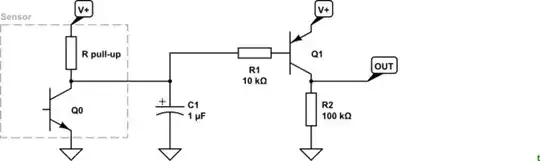
When the TSOP detects the IR carrier, it pulls its output low. This is done with fairly low impedance, so discharges the capacitor quickly. When it stops pulling low, the capacitor gets charge up again thru R1 and the internal pullup in the TSOP. Those together are much higher impedance, so the capacitor charging up takes longer. Transistor estimated that Q1 will stay on for about 100 ms after the TSOP releases its output.

Olin Lathrop
  • 313,258
  • 36
  • 434
  • 925
  • Thank you so much. If you could you please further enlighten me about the role of the capacitor. @Transistor mentioned that the IC will get 1 pulse provided that there is at least 100ms between presses. The output of the TSOP is high when there's no IR signal. So if I understand correctly, the electrons from the positive terminal of the capacitor travel to the output pin creating positive charges (holes). But does the electrons of the PNP's base pin also travel to the TSOP's output pin at the same time? And if that's the case, there's current from the collector to the emitter of the PNP to IC? – user1764381 Nov 12 '17 at 23:57
  • 1
    @user: See addition to answer. – Olin Lathrop Nov 13 '17 at 11:39