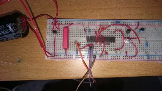
 I'm experimenting with an ATmega328p on a breadboard using the standard Arduino bootloader. I'm looking at the power consumption as I want to power the device from a solar panel and a large cap. I've got a sketch that get's the device into the lowest power sleep mode. I'm measuring the power supply current and this drops to 23uA with the brownout detector enabled when the supply is above the brown out threshold of 2.7V. If the power supply is adjusted to below the brownout detector threshold then the power supply current jumps up to 881uA. I've tied all floating pins to ground but this doesn't seem to help. Is this expected behaviour or am I doing something wrong ?
/*
 * Sketch for testing sleep mode with wake up on WDT.
 * Donal Morrissey - 2011.
 *
 */
#include <avr/sleep.h>
#include <avr/power.h>
#include <avr/wdt.h>

#define DIVIDER_PIN (13)
#define LOAD_PIN (12)

volatile int f_wdt=1;


/***************************************************
 *  Name:        ISR(WDT_vect)
 *
 *  Returns:     Nothing.
 *
 *  Parameters:  None.
 *
 *  Description: Watchdog Interrupt Service. This
 *               is executed when watchdog timed out.
 *
 ***************************************************/
 ISR(WDT_vect)
 {
   if(f_wdt == 0)
   {
      f_wdt=1;
   }
   else
   {
     // Serial.println("WDT Overrun!!!"); // this shouldn't happen
   }
}


/***************************************************
 *  Name:        enterSleep
 *
 *  Returns:     Nothing.
 *
 *  Parameters:  None.
 *
 *  Description: Enters the arduino into sleep mode.
 *
 ***************************************************/
 void enterSleep(void)
 {
   byte keep_ADCSRA;

   keep_ADCSRA=ADCSRA; // save adc register
   ADCSRA=0; // disable A/D converter

   set_sleep_mode(SLEEP_MODE_PWR_DOWN);   // SLEEP_MODE_PWR_DOWN for lowest power consumption
   sleep_enable();

   /* Now enter sleep mode. */
   sleep_mode();

   /* The program will continue from here after the WDT timeout*/
   sleep_disable(); /* First thing to do is disable sleep. */

   /* Re-enable the peripherals. */
   power_all_enable();

   ADCSRA = keep_ADCSRA;                          //re-enable A/D converter

 }

void setup()
{

  // All pins as outputs set to 0 to save current
  //for (byte i = 1; i <= A5; i++)
  //  {
  //  pinMode (i, OUTPUT);
  //  digitalWrite (i, LOW);
  //  }

  pinMode(LOAD_PIN, OUTPUT);
  digitalWrite(LOAD_PIN, 0);
  pinMode(DIVIDER_PIN, OUTPUT);
  digitalWrite(DIVIDER_PIN, 0);

  pinMode(PD0,INPUT); // rxd input for serial comms
  pinMode(A0,INPUT); // a0 needed as input to read cap voltage

  Serial.begin(9600);

  /*** Setup the WDT ***/

  /* Clear the reset flag. */
  MCUSR &= ~(1<<WDRF);

  /* In order to change WDE or the prescaler, we need to
   * set WDCE (This will allow updates for 4 clock cycles).
   */
  WDTCSR |= (1<<WDCE) | (1<<WDE);

  /* set new watchdog timeout prescaler value */
  WDTCSR = 1<<WDP0 | 1<<WDP3; /* 8.0 seconds */

  /* Enable the WD interrupt (note no reset). */
  WDTCSR |= _BV(WDIE);

 // Serial.println("Initialisation complete.");
 // delay(100); //Allow for serial print to complete.
}


unsigned int val=0;
double voltage;
void loop()
{
  if(f_wdt == 1)
  {
    /* Don't forget to clear the flag. */
    f_wdt = 0;

    /* Re-enter sleep mode. */
    enterSleep();

    // power up the voltage divider and take a reading
    digitalWrite(DIVIDER_PIN, 1);
    delayMicroseconds(250); // settling time
    val = analogRead(A0);
    digitalWrite(DIVIDER_PIN, 0);
    voltage=(val*18.0)/10.24;

    if (voltage>500.0) {
      digitalWrite(LOAD_PIN,1);
      delay(100);         // 0.1 second on
      digitalWrite(LOAD_PIN,0);
    }
  }
}