Does the charger list a "trickle" or "float charge" current? Also, aside from the "accidental short", has this charger properly worked?
I believe that this circuit limits the current via the transformer's impedance, Rblown and battery's internal resistance and is protected by the fuse and is uncontrolled in voltage. As you mention in your description, the circuit is there to control the battery full light.
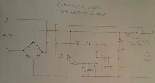
Starting backwards from the light: The zener diode, 19R and 200R form a supply to allow the "full" diode to turn on when Q9014 is off. Q9014 is controlled by the output of the current sense amplifier formed by Rblown, 10k and Q9015. The voltage across Rblown from the charging current turns Q9015 on. When Q9015 is on, current flows through the 2.7k and 100k which turns on Q9014 (and turns off the "full" led). As the battery charges, Q9015 will start to turn off, thus reducing the current through 2k7 and 100k, which will result in Q9014 turning off (and the full led turning on). The electrolytic capacitor provides some filtering to assure that Q9014 stays on and prevent flickering by the "full" led.
The 4148's and 4k7 resistor form a supply for 9014 to pull its collector up above the voltage formed by the zener & resistors. The second 4148 that is connected to Q9014's collector prevents the power LED from turning off when Q9014 turns on. Note that I believe this supply is intentionally connected to the ac input because power diode bridge has a higher Von than the 4148's.
So, the value of Rblown is determined by the "full" current level and the required voltage threshold to cause Q9014 to turn on and is limited by the power dissipation at full charging current.