4

I've been experimenting with a half-bridge converter and there is something that I don't understand: what is the purpose of the capacitance and extra winding in the gate base driver?

enter image description here

The extra winding is magnetically coupled with the other winding of the driver transformer.

ocrdu
  • 9,195
  • 22
  • 32
  • 42
Masood
  • 81
  • 1
  • 3
  • 1
    The capacitor you have circled is here to prevent the transformer primary-side winding to be dc-biased during switching operations. Usually, there are two caps (http://www.runonielsen.dk/Half_bridge_control.pdf). Now, regarding the link to the gate-drive transformer, it looks like a kind of speed-up circuit further biasing $Q_1$ and $Q_2$ as soon as they start conducting. It could be the case, especially if these two bipolar transistors need a large base current to turn on. I would personally use MOSFETs instead and remove this winding. – Verbal Kint Jul 13 '17 at 13:26
  • thanks for your help. but if the extra winding is used as speed-up circuit, then after turning the bjt on it will never turn off. Also I have a half bridge converter and I shorted this winding and it did not work at all. – Masood Jul 13 '17 at 16:49
  • Your remark regarding the speed-up action makes sense. If you want to get rid of this winding, do not short it as you short the drive also! Leave it unconnected instead (or load it with a resistor) but connect the left-side of the current sense transformer to the half-bridge node so that the controller still senses the current. – Verbal Kint Jul 13 '17 at 17:09
  • You are right, shorting the winding is not a good idea. – Masood Jul 13 '17 at 18:15
  • I've read the article (runonielsen.dk/Half_bridge_control.pdf). But there is nothing in it about the mentioned capacitor. It describes about two capacitance (C5 & C6 in picture above). I think C10 (mentioned capacitor) is used to prevent high voltage transformer to saturate, is it right? – Masood Jul 13 '17 at 18:26
  • Is it possible that the combination of the capacitor and extra winding is used to form a resonant converter? – Masood Jul 13 '17 at 18:32
  • To get rid of the winding I connected the left side of current sense transformer to the half bridge node, but power supply did not work. Also I twisted the winding in different way (from clock wise to counter clock wise) and again the power supply did not work. – Masood Jul 14 '17 at 06:32
  • I checked with colleagues and they confirmed this is a speed-up circuit which ensures self-relaxation at start-up until the TL494 takes over to directly drive the transistors. I don't think it is necessary in converters in which an auxiliary power supply is already there but here there is none apparently. You have to be cautious when probing waveforms because this converter seems totally non-isolated. – Verbal Kint Jul 14 '17 at 12:03
  • thanks a lot I do research and I found it. It is called proportional drive circuit. At first TL494 and Q3 and Q4 try and turn the high voltage transistor on, then this winding keeps the transistor on. Because collector current of high voltage transistor is not constant base current must be proportion to that. So proportional drive circuit is used to have maximum efficiency. – Masood Jul 15 '17 at 06:30
  • Glad this is understood, you perhaps can acknowledge the answer then. Also, if you have found a link with more information on this subject perhaps could you kindly share it with the technical community. Thank you. – Verbal Kint Jul 15 '17 at 08:34
  • This may be handy to read http://www.qsl.net/xq2fod/Electron/PS40/PS40.html And this http://obrazki.elektroda.pl/2337604400_1500222128.png – G36 Jul 16 '17 at 16:22
  • To provide an info for the purpose of C10: That capacitor blocks DC and it's called "DC blocking capacitor". Remember a H-bridge, replace Q1-Q2 or Q3-Q4 pair with equal capacitors (and of course, the parallel resistors), and put the primary winding as a load. Yes, now you have a half bridge converter. Since the side that capacitors are placed in has DC all the time and we don't want it to reach to the transformer, a capacitor is used for blocking. – Rohat Kılıç Nov 15 '17 at 05:53

2 Answers2

5

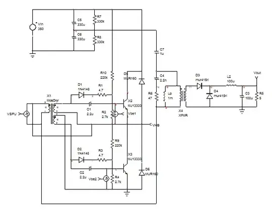
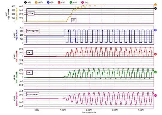
The below circuit shows a quick simulation file concentrating on the power section only. The thing is to crank the power supply by forcing a self-relaxing activity through the extra winding you mention. An initial start-up current is given by \$R_2\$ which biases \$Q_1\$ at power-up. Given the presence of the speed-up winding and its polarity, this strengthens the biasing of \$Q_1\$ until its collector current no longer rises given the available base current. As \$\frac{d\phi}{dt}=0\$ in the transformer, the transistor blocks because the extra bias disappears. The polarity reverses on the speed-up winding, effectively blocking \$Q_1\$ and now biasing \$Q_2\$ until a new cycle repeats. Then I believe the TL494 will soon drive operations once the auxiliary supply is alive. The start-up sequence seems to be at low frequency and nicely oscillating considering the arbitrary values I put there. It should be enough to understand the role of this extra winding which blindly (there is no over current protection or over voltage protection in the sec. side either) ensures a self-relaxing start-up until the TL494 takes over. I have looked at the Czech site in which the owner gathered a lot of power supply schematics (nice collection!) and it was the way cheap ATX power supplies were designed a while ago. I however do not see the need for a self-relaxing circuit like this one when a 5-V USB auxiliary power supply is present in the silver box as this power supply starts first and then provides a \$V_{cc}\$to the control circuit. Nowadays, most ATX boxes uses a 2-SW forward converter with MOSFETs and a dedicated control section powered from a standby power supply.

enter image description here

enter image description here

Verbal Kint
  • 21,968
  • 1
  • 18
  • 55
  • Good answer! By the way, I've asked a similar question nearly a year ago but the extra winding in my question serves a different purpose. Interesting to see such a different approach. So I fav'd the question and answer. I also want to append some extra info: ... – Rohat Kılıç Nov 15 '17 at 05:15
  • ... I however do not see the need for a self-relaxing circuit like this one when a 5-V USB auxiliary power supply is present. Actually, there's always the extra winding in the gate-drive transformer even if the power supply has an independent SB supply circuit (example). But, as I said, those windings serve a different purpose: Since the bridge switches are BJTs, the switching losses will be much higher than MOSFETs. So those extra windings provide a soft transition of primary current (think of a resonant pump) and decrease the the switching losses. ... – Rohat Kılıç Nov 15 '17 at 05:25
  • ... And yes, those extra windings are not needed when MOSFETs are used and provided an independent SB supply circuit. By the way, the most big disadvantage of the OP's circuit is the absence of the standby power supply circuit because the circuit "may" be unstable on light loads even if the FAN is used as a dummy load. Nowadays, most ATX boxes uses a 2-SW forward converter with MOSFETs. True. But, half-bridge and full-bridge are the most common topologies for new designs due to the need of 80+ GOLD, PLATINUM or TITANIUM certificates for high power (>500W) supplies. – Rohat Kılıç Nov 15 '17 at 05:35
-1

No one answered the specific question "what is the purpose of the capacitor". The answer is: to prevent transformer dc bias in 110-V grid operation.

Cubrilo
  • 359
  • 1
  • 4
  • 14
  • 110 V grid has nothing to do with it. – winny Nov 14 '17 at 17:39
  • 1
    Your answer would be true without "... in 110-V grid operation" phrase. – Rohat Kılıç Nov 15 '17 at 05:52
  • Write that to Mr. Horowitz & Mr. Hill, they will be happy to learn something new. The Art of Electronics, p. 655 says "The dc blocking capacitor CB in the H-bridge prevents flux imbalance and consequent core saturation; for the half-bridge the series pair of capacitors serves the same function, while acting also as the input storage capacitor." – Cubrilo Nov 15 '17 at 13:17
  • 1
    @Cubrilo I agree with H&H, but your addition to the end of "in 110-V grid operation" is not in H&H. – W5VO Nov 20 '17 at 13:44
  • "110-V grid operation" connects mid-point directly to the grid, so "the series pair of capacitors" lose their function described by H&H. Another reference is TI, they made and actually sell their "LM5039 Evaluation Board" WITHOUT series capacitor because -SURPRISE- they don't need it. I repeat: the capacitor is required only for "110-V grid operation" or "voltage doubler", if you like it. – Cubrilo Nov 21 '17 at 18:39
  • 1
    @Cubrilo You're talking about the supplies having 110V/220V selection switches. But blocking capacitor usage is not related to this. Yes, the two series capacitors provide the midpoint and an inequality caused by them leads to flux imbalance (remember the Half- and Full- Bridge converters' cores operate on 1st and 3rd quadrants of their BH loop) and the BH loop to "walk" which we never want. And the series blocking capacitor is placed to avoid this. But come on! This is not related to the voltage doubler! – Rohat Kılıç Nov 22 '17 at 13:31
  • 1
    @Cubrilo Did you really think about why the series blocking capacitor is not needed in LM5039 eval board? You said because -SURPRISE- they don't need it, but it is not related to 110V operation. The series blocking capacitor is not needed because LM5039 measures the average current (via T2 current transformer and BR1 bridge rectifier), thus the potential flux imbalance is automatically avoided. You can check it from p.12 of the datasheet. – Rohat Kılıç Nov 22 '17 at 13:47
  • 1
    @Cubrilo Result: If current mode control is used then the series blocking capacitor is not needed. You can check this from any academic or non-academic source you want. Two good examples: Switching Power Supply Design (from Abraham Pressman) and Switchmode Power Supply Handbook (from Keith Billings). – Rohat Kılıç Nov 22 '17 at 13:52
  • @Rohat Kılıç I've never mentioned current mode control, and what it needs. LM5039 is "Voltage-mode Control" as stated in TI datasheet, I believe they know better about control modes. The OP attached schematic with TL494 which is also voltage mode controller. You cannot claim that controller uses current mode control just because it measures primary current, because then there would be no voltage mode controllers left on Earth. – Cubrilo Nov 28 '17 at 18:38
  • @Cubrilo I've never mentioned that LM5039 is a current-mode controller or not. I only told that LM5039-based bridge converters do not need a series blocking cap because LM5039 applies average primary current limiting thus maintains the balance of the center point (Datasheet p.12, the statements above Fig.14). As you might see, this is not about 110V grid operation. That is what I'm saying. – Rohat Kılıç Nov 29 '17 at 05:19
  • @Cubrilo Final words: Current-mode control and average current-limiting are totally different things. If the controller uses current-mode control for primary PWM then there's no need for a series blocking capacitor. This explains why there is a series blocking capacitor in the circuit in OP's question. – Rohat Kılıç Nov 29 '17 at 05:22