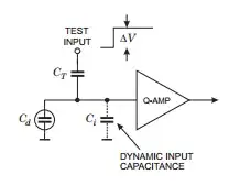
I'm performing tests of the detector's breakout electronics. These are printed circuit boards that will take signals from inside an ionization detector to the rest of the data acquisition apparatus.
The key component of these circuits is a capacitor, upon which charge is collected which induced a voltage across the capacitor. This charge is the result of ionization events inside the detector, and specifically the ionized electrons being collected by wires inside the chamber.
I have a BNC Model BH-1 pulse generator (link) and I have tried hooking it up directly to the circuit boards in question. The output from the boards, viewed on an oscilloscope, is signal-like, and responds to manipulation of the pulse generator dials, as one would expect. But it's heavily warped by the interference of the two involved RC circuits.
The pulse generator doesn't simulate the expected charge collection correctly. I want it to produce a charge buildup on the capacitor as a real event inside the detector would. Perhaps I require additional circuit components to make this work? Or I don't understand the problem myself in full detail? Any help or identification of my points of ignorance would be appreciated.
