I am trying to simulate this circuit I saw here:

However, when I simulate it, the "mid-point" does not behave like the blue line in the above picture. You can check the simulation here:
Is the original picture wrong? Am I missing something?
I am trying to simulate this circuit I saw here:
However, when I simulate it, the "mid-point" does not behave like the blue line in the above picture. You can check the simulation here:
Is the original picture wrong? Am I missing something?
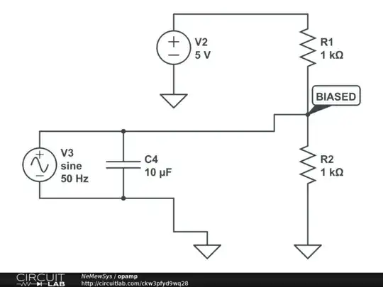
You have connected the output of your simulated CT to GND. This is not how the original circuit is wired.
One side of the CT output in the original circuit is connected to the bias point, the other side is the input to the Arduino.
Connect the capacitor across the bias resistor, and one side of the CT output to the Arduino A/D input.
https://www.circuitlab.com/circuit/595a448d3mdx/updated-circuit/
If you are trying to measure current, then don't forget the burden resistor. If you are trying to measure the voltage, then use a normal transformer with a 3V output.
Never make measurements directly from the mains - remember mains can be lethal! Take care in what you are doing.
Those circuits don't match up.
The Bottom leg of the transformers output is tied to the mid point and has a load resistor across it. It's the upper leg of the AC source that will follow the blue line.
Midpoint should remain at a stable 2.5 V (the bottom red line in the graphs). That is the source of the voltage offset.