0

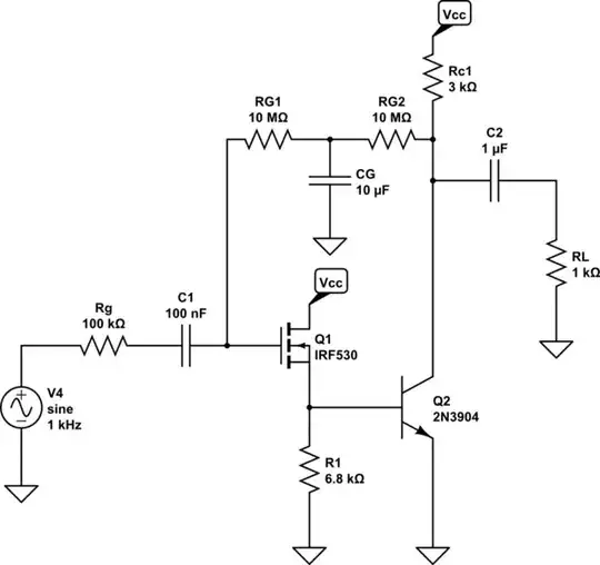
In the following circuit, to considerably reduce the effect of RG on Rin and hence on amplifier performance, another 10MΩ resistor was added in series with the existing one and a large bypass capacitor between their joint node and ground was placed. What will Rin, AM, and fH become? enter image description here

Here's my attempt:

enter image description here

\$V_i-V_x+V_o-V_x=10M\cdot V_x/(j\omega C)\$

I know \$V_o/V_i\$ of the original circuit, in midband frequency, which shouldn't change in this case. Let's denote that \$x\$.

I can hence infer that:

\$K_1=V_x/V_{in}=(1+x)/(2+10M/j\omega C)\$

and

\$K_2=V_o/V_x=(2+10M/j\omega C)\cdot x/(1+x)\$

Therefore,

\$M1_{in}=10M/(1-K_1)\$

and

\$M1_{out}=10M \cdot K_1/(K_1-1)\$

Similarly,

\$M2_{in}=10M/(1-K_2)\$

and

\$M2_{out}=10M \cdot K_2/(K_2-1)\$

Is this the right way to solve this? Is there a simpler approach? I figured now I could easily determine \$R_{in},f_H\$, as requested. enter image description here

peripatein
  • 399
  • 6
  • 16
  • Why don't you use a sim? It's a basic circuit and a sim should perform really well. – Andy aka Jun 10 '17 at 09:36
  • @Andy aka I am expected to solve it analytically – peripatein Jun 10 '17 at 09:38
  • How to solve this: 1) find the DC solutions for Q1 and Q2 because you need to know their gm. 2) draw the small signal equivalent circuit of Q1, Q2 and find the gain from Vi to Vo. 3) now that you know Vo/V1 solve with 100 k Rsource and Rg in place. – Bimpelrekkie Jun 10 '17 at 10:05
  • @Bimpelrekkie I already did that but now I need to assess how the new configuration would affect my results. In my attempt I tried to elaborate how to account for the changes. Does my work make sense to you? – peripatein Jun 10 '17 at 10:18
  • No, I do not see how you can have a 2nd 10 Mohm resistor in there. Study how to solve amplifiers with feedback and apply that. – Bimpelrekkie Jun 10 '17 at 10:24
  • @Bimpelrekkie The question stated explicitly "another 10MΩ resistor was added in series with the existing one and a large bypass capacitor between their joint node and ground was placed" – peripatein Jun 10 '17 at 10:26
  • You don't ever need to know Vx, at DC you just solve the circuit as Rg= 2*10Meg, at AC Vx is grounded. – sstobbe Jun 10 '17 at 12:00
  • @sstobbe so in AC the value of RG would simply be 5M and I could use Rin=5M/1-K, where K=midband voltage gain? – peripatein Jun 10 '17 at 12:05
  • Bypass cap means short circuit at signals of interest. So you have a 10Meg resistor to ground on the input and a 10Meg resistor to ground on the output. No resistor connects the output to input, since the bypass cap shorts to ground. – sstobbe Jun 10 '17 at 12:09
  • @sstobbe why couldn't they be evaluated in parallel, hence my 5M? – peripatein Jun 10 '17 at 12:12
  • Its because the only have one terminal connected together, at the bypass cap. The other terminal of the resistor is connected to different parts of the circuit. – sstobbe Jun 10 '17 at 12:15
  • @sstobbe Okay, so is my new Rin=10M, new fH=1/(2pi(10M+100k)), new AM=old AM (as I was told that in determining the small signal voltage gain I could ignore RG)? – peripatein Jun 10 '17 at 12:17
  • Yes Rin=10M, low freq fL is set by Rin and C1 – sstobbe Jun 10 '17 at 12:26
  • @sstobbe Right, silly me, what I meant to write was rather fH=1/(2pi(100k+Min)), where Min=5M/1-K and where K=AM, midband voltage gain. Is that correct now? – peripatein Jun 10 '17 at 12:32
  • Millers theorem only applies to Cu on Q2. So fH will either be due to Cgd on Q1 on M*Cu on Q2 – sstobbe Jun 10 '17 at 12:38
  • @sstobbe Here's another attempt -- fH=1/(2piCgd*(Min+100k)). Is it correct now? – peripatein Jun 10 '17 at 13:12
  • fH=1/(2piCgd*(10Meg||100k)), Min you refer to is 10Meg? – sstobbe Jun 10 '17 at 13:18
  • @sstobbe Let's see if I understand: before RG was changed, fH was 1/(2piCgd(Min||100Kohm)), where Min=10M/1-K and K is midband voltage gain. This yielded fH=2.075MHz. After another 10M was added in series with a bypass cap. fH changed to 1/(2piCgd10Meg||100K), yielding fH=1.607MHz? – peripatein Jun 10 '17 at 13:28
  • Sounds reasonable, also note the gain is slightly different for the two cases, as Rsig divides into Min – sstobbe Jun 10 '17 at 13:52

2 Answers2

1

Is there a simpler approach?

My simple approach is that with the original circuit you have negative feedback at all frequencies therefore the input impedance at the gate is close to zero ohms. That's how negative feedback works. It's a virtual earth as per an op-amp virtual earth.

With the modified feedback (and C being a large capacitor as stated) there is only negative feedback at DC and very low frequencies hence, at significantly higher frequencies, there is no feedback hence the input impedance is 10 Mohm (the left resistor in your added/modified circuit).

That's about as simple an approach as you can get.

Andy aka
  • 456,226
  • 28
  • 367
  • 807
0

The circuit looks like this:

schematic

simulate this circuit – Schematic created using CircuitLab

DC operation point is \$I_{D1} \approx \frac{0.7V}{6.8kΩ} \approx 100 \mu A \$

And \$V_{GS1} = V_T+\sqrt{\frac{I_D}{0.5K'n}}\approx 1.3V\$ and \$ I_{C1} \approx \frac{5V - (0.7V + 1.3V)}{3kΩ} \approx 1mA \$

And for AC signal

schematic

simulate this circuit

And from inspection we can see that \$ R_{in} = R_{G1} = 10MΩ\$

And the AC voltage gain is:

$$ A_V = -\frac{R_{G1}}{R_g + R_{G1}} *\frac{R1||((\beta+1)*r_e)}{R1||((\beta+1)*r_e) + \frac{1}{g_{m1}}}*\frac{R_{C1}||R_L||R_{G2}}{r_e}*\frac{\beta}{\beta+1} \approx -18.8$$

G36
  • 14,576
  • 1
  • 20
  • 36
  • And the MOSFET gm1 is ? – G36 Jun 10 '17 at 15:49
  • You're right, except that I got approx. -19.1, instead of approx. -18.8. By the way, if I wished to find fL of this circuit, hence to determine the frequency of the poles due to C1 and C2, could I use OCTC to obtain this: fL=1/(2pi[C1(100K+3K+10M)+C2(4K)])? Would that be correct? – peripatein Jun 10 '17 at 16:00
  • But for FL we suppose to use Short-Circuit Time Constants – G36 Jun 10 '17 at 16:05
  • AS for FL we have FL1 ≈ 0.16/((Rg+RG1)C1) ≈ 0.16Hz and FL2 ≈ 0.16/((Rc+RL)C2) ≈ 40Hz hence FL ≈ 40Hz – G36 Jun 10 '17 at 16:23
  • And for FH we have two poles Fh1 ≈ 0.16/( (Rg||RG1) Cgd+ Cgs(1 - A1) ) ≈ 0.16/(100k * 1pF+1pF(1 - 0.666)) ≈ 0.16/(100k1.4pF) ≈ 1.14MHz. Where A1 is Q1 gain. – G36 Jun 10 '17 at 16:53
  • Fh2 ≈ 0.16/(R1||rpi||1/gm1 * Cbe + Cbc(1+A2)) ≈ 0.16/(1k 10pF + 0.8pF30) ≈ 0.16/(1k34pF) ≈ 4.7MHz where A2 is Q2 gain – G36 Jun 10 '17 at 16:55
  • What's Cbe? It's not given in the question – peripatein Jun 10 '17 at 18:09
  • Not directly, but if we know Ft and gm we can find Cbe = gm/(2pi*Ft) - Cbc – G36 Jun 10 '17 at 18:27
  • Do I find the total fH by 1/[sum(time constants)] or do I use the square root formula? – peripatein Jun 10 '17 at 19:37