In reality there is some leakage R in the transistor ("Early" effect) thus at turn off, the inductor current develops a large +ve spike from a "low side" NPN switch turned off. ( and negative spike if PNP "high side" was used.)
If coil L was 200mH and Ic was 10mA and R leakage=1M then current decay time constant is T=L/R 0.2mH/1M =0.2us = then Vpk=LdI/dt 0.2H* 10mA /0.2us = 4kV.
But since above Vce(max) is a zener-like breakdown it would absorb the spike but the high dV/dt causes EMI, so a reverse diode clamp is connected to the collector to supply to drain the current with it's much lower ESR in a longer duration defined by T=L/R(coil) where the diode Rs or ESR is similar to the transistor if both have the same power rating can be neglected as the coil resistance might be around 1k (depending on 12V relay) while transistor and diode ESR <<10 Ohms @10mA.
The area enclosed of the coil current to ground and the diode current loop to Vcc and gnd both become loop antenna for EMI radiation so close coupling of these tracks is important to remember in future for noise issues with decoupling cap nearby on Vcc.
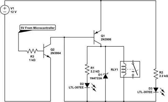
For the advanced reader, I included the above details and below simulation with the diode switched open during the trace and included an internal 100V zener for the Vce breakdown voltage.
Upon close examination below, one can see the std. glass clamp diode exists, next to relay.

Although my 5V clock was 1kHz to show the rise time and decay time are the same limited by the L/R ratio of the relay coil, one would expect with **no load* the relay would last 1e6 to 1e7 operations max( Ref OMRON) and would fail after 1e3 to 1e4 seconds and with a reactive load fail in minutes at this rate with severe arcing on contacts. buzzzzz
