I have been having some difficulty recently when trying to measure very low currents when using a small sense resistor.
I am trying to measure in the range of uA (1 - 150uA) with a supply voltage of 3.3V. Now, usually this is not too much of an issue, but the problem I am getting here is that this particular project uses a WiFi module that peaks at around 600mA.
I am needing to use a small current sense resistor (0.1R) because I just can not afford the voltage drop over higher values at peak current consumption. I tried a few different current sense amplifiers but found them to be not quite accurate enough at these small levels. I eventually settled for a chopper stabilised amplifier (TLC2652) because even though it wasnt a specific current sense amplifier, it offered my <1uV offset which I thought was great. I set it up as a differential amplifier with a gain of 100 however, it still struggled with accuracy when getting tot he very low current range. Annoyingly, it works perfectly when using a 1R current sense resistor, but as previously mentioned, I cannot afford this voltage drop. With the 0.1R resistor, it is fine untill it gets below round about 20ish uA then it gets a bit noisy.
Does anyone have any suggestions on a good workaround for this to get it to work?
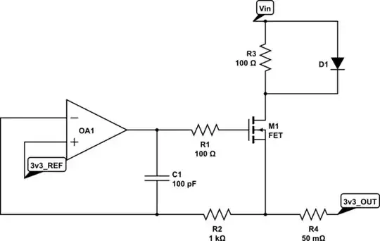
Here is the way I have it set up:
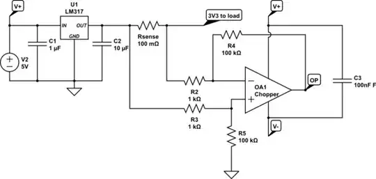
simulate this circuit – Schematic created using CircuitLab
I will say that it is not highly critical for it to be supremely accurate, this is just part of a circuit to do functionality checks, so I am fine with it being a little noisy in these very low currents, however, it does not stop my curiosity and my desire to find a way to solve it!
I hope I have worded my question alright, please let me know if I have missed any information or if there is something I have not explained correctly.
Also, as a side note, I must state I am still learning electronics so apologies if I have done something incorrectly or done something that some more experienced people may find silly!