1

Currently we are measuring the position of a mechanical beam by illuminating it with light from an IR diode and using two phototransistors to measure the difference between light passing over and under it. The combined signal then feeds a PID loop which holds it in position.

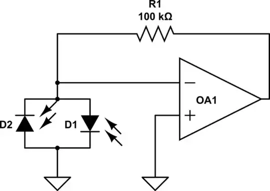
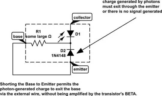
We are using phototransistors (OP803SL) configured like this: Phototransistor config

With T1 and T2 going to a differential amplifier

Frequency response is under 50Hz. I am looking for a lower noise alternative, either in terms of parts (eg photodiode) or configuration.

Any suggestions?

Dirk Bruere
  • 13,723
  • 9
  • 54
  • 115
  • 1
    Would it be sufficient to add a low-pass filter to the output? – nibot Mar 02 '17 at 16:29
  • I'm confused by your schematic diagram. Why is the transistor emittor connected directly to the base? Why is there no resistor to ground? – nibot Mar 02 '17 at 16:31
  • @nibot you don't need to supply base current, light does that. –  Mar 02 '17 at 16:47
  • @BrianDrummond What about using it in pure PV mode? – Dirk Bruere Mar 02 '17 at 17:04
  • Base connectors for phototransistors are usually used just to create biases. They are not the output of the phototransistor. – Scott Seidman Mar 02 '17 at 17:11
  • If you're having noise problems (which seems odd) then you need either a better illumination source or a better detector light collection setup. – WhatRoughBeast Mar 02 '17 at 17:32
  • 1
    With the base shorted to emitter, the "transistor" function does not work. Try letting the base float. – analogsystemsrf Mar 03 '17 at 06:42
  • 1
    This question seems entirely appropriate for this site. I'm confused as to why it was closed as off-topic. – nibot Mar 10 '17 at 17:10
  • 1
    @nibot I wrote "I am looking for a lower noise alternative" and the usual up their own arse mods read it as a reccommendation for a specific device rather than what I intended, which was an alternative circuit idea eg photodiode configuration. Anyway, found my answer so I can't be bothered to re-edit – Dirk Bruere Mar 11 '17 at 17:25
  • @DirkBruere What was your solution? – nibot Mar 12 '17 at 05:47

2 Answers2

1

schematic

simulate this circuit – Schematic created using CircuitLab Photodiodes back-to-back can be used in a transimpedance amplifier, where the op-amp maintains zero volts at diode junction. Output voltage will go positive for more illumination at D2, and negative for more illumination at D1. R1 can be increased for more gain. R1 may require a parallel capacitor of very small value to remain stable at high frequency.

glen_geek
  • 25,809
  • 1
  • 23
  • 53
  • A disadvantage is that output only tells you illumination difference of D1, D2. Higher illumination will increase PID loop gain, but this circuit gives no way of measuring infrared amplitude. – glen_geek Mar 02 '17 at 16:53
1

I view a phototransistor to be like this:

schematic

I have used the base to control the collector operating point, so as to null out sunlight and 60Hz "noise". Otherwise I leave the base floating.

analogsystemsrf
  • 34,253
  • 2
  • 19
  • 48