The "sometimes stays on" action is what is called "hysteresis". This is designed to stop the light flashing on and off when it is on the verge of night or day.
Once it is on it adjusts its trigger level point such that it needs to get somewhat lighter befre it will go off again.
Once it is off it adjusts its trigger level point such that it needs to get somewhat darker lighter before it will go on again.
When you adjust the conditions to be "just right" you dro it into a "twiligh zone" (literally in this case" where it needs more dark or more light to cause action.
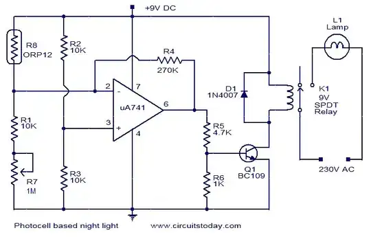
Here is a typical nightlight control circuit with hysteresis.
The ORP12 at R8 is a light variable resistance.
R7 is a sensitivity control.
As light level varies the voltage at the R8/R1 boundary varies.
The opamp compares this voltage with the voltage from R2 / R3 divider and switches when the ORP8 controlled voltage transitions past that voltage i either direction.
Hysteresis is meant to be added by voltage from the output of the opamp, via R4, back to its input. The interesting this is that they have connected it to th wrong plac !!! :). R4 should connect to opamp pin 3 = non inverting input and not to pin 2 = inverting input. When it is connected to the + input, anything that happens at the output is fed back as positive feedback and enhances the action. This exact circuit diagram (same drawing without change) can be found in many locations on the internet with some mentioning hysteresis - which it has not got.
So - this is an example of the sort of cct that may be in your light - but they sound like they have connected it correctly in your case.
This one does it correctly but its action is slightly harder to follow.
Circuit from here with an OK discussion. He specifically notes
R5 R6 & R7 as being involved in setting the amount of hysteresis, which they are. Bigger version of diagram here
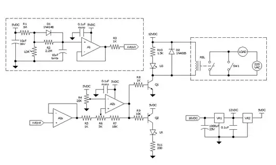
Circuitry in box at top left varies the "attack & decay" rates of the LDR (ligh dependant resistor) effect - see his text for why.