I'm a newbie to transistors. Could anyone explain why my set up doesn't work ? The transistor is a 2N2222 NPN BJT, and the microphone is just a standard earbud. The loudspeaker is just one I ripped out from a toy.
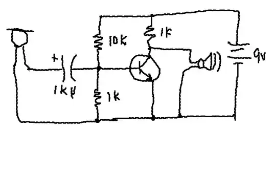
I'm a newbie to transistors. Could anyone explain why my set up doesn't work ? The transistor is a 2N2222 NPN BJT, and the microphone is just a standard earbud. The loudspeaker is just one I ripped out from a toy.
Several things:
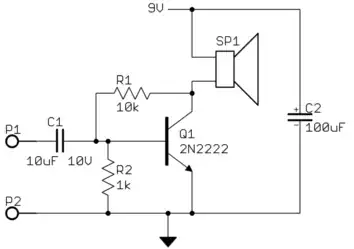
This isn't a great circuit for a number of reasons, but it is something you should be able to rig up with what you have and get some results. Don't expect it to amplify from a microphone. It doesn't have enough gain for that. You can probably connect a similar speaker as the input, put your ear right up to the output speaker, and hear something when you gently scratch the input speaker with your finger.
Place a capacitor (100uF?) in series with speaker.
This stops speaker DC shunting collector voltage)
Put 33 ohm resistor emitter to ground.
Vb ~= 1k/(1k+10k) x 9V = 0.8V.
Vbe ~=0.6V.
So need to deal with 0.2V extra.
Add Re so 6 mA flow so V1k in collector = 6V drop .
Re = V/I = 0.2/0.006 = 33 ohms.
Transistor now draws ABOUT 6mA so drop across Rc = 1k = V = IR = 6 mA x 1k = 6V.
So Vc = 9V-6V = 3V ~~~
Connect from 10 uF to 100 uF across emitter resistor.
This bypasses AC signal around Re.
Re is now just for DC bias.
Circuit will draw ABOUT 6 mA.
Vcollector will be ABOUT 3V.
Gain will be ABOUT 230.
Gain ~~= 38.4 x V across Rc = 38.4 x 6 =~ 230
Due to non idealities the above may not quite work, so ...
If Vcollector < 1V increase emitter resistor.
If Vcollector > 3V decrease emitter resistor.
With a gain of 230 or so you need about 20 mV pp signal in to saturate this amplifier. We set Vc = 3V so 3V negative is max swing available. So Vin going positive by 3V/230 = 13 mV will saturate collector voltage and drive collector to groujd. 10 mV max is about right.
If we had set Vc at mid rail we would have more swing but less gain. Gain goes up as Vc static rises. As above Gain = 38.4 x Vc_static.
Close enough to "max gain possible~~= 40 x Vbattery. (a bit less actually. )
As Olin has noted - the speaker load will prevent the potential gain being achieved. Adding an emitter follower as a power amplifier (not a voltage amplifier - it has a gain slightly less than 1) will allow the speaker to be driven at higher power AND the amplifier to achieve closer to its maximum gain.
An emitter follower is not an ideal power amp and the one transistor amplifier is far from an ideal audio amplifier BUT the 2 transistor circuit shows what can be achieved.
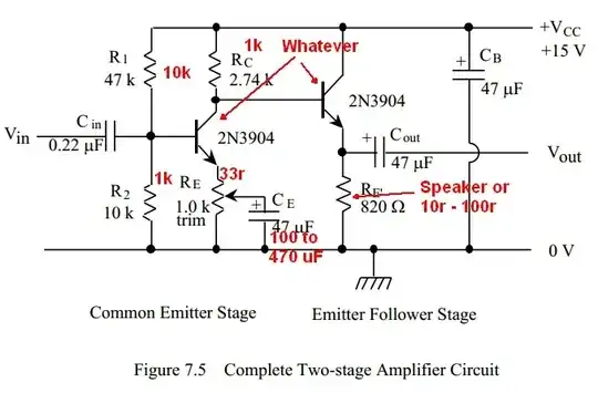
Here is an excellent laboratory experiment sheet from University of Colorado, Boulder. Physics 330 - Experiment 7 - Transistor Amplifiers
It not only goes through the design but provides a circuit that will suit your need with minor modifications, as shown below.
In your application the bigger Ce is the better - it sets the low frequency gain and even eg 470 uF would be good. (A 10V 470 uF Aluminum electrolytic capacitor is cheap and commonly available). Leave base resistors and emitter resistor as I noted previously.
I have left their component values on black and added "our" ones in red.
The speaker may be connected to Vout OR can replace Re' (right hand transistor emitter resistor). They, too, should have named their components.
There are a few problems with your circuit.
First of all, your speaker has low resistance (usually 4-8 Ohms), so in the current citcuit it basically shorts out the transistor. To avoid that, connect a capacitor in series with the speaker. The capacitor should be 100uF or more.
Second, the collector resistor is way too high resistance. As I said, the speaker has low resistance, so it needs a lot of current. You probably would get something like 0.5mW, which may not be audible.
Also, there usually is a resistor (and a capacitor in parallel to it) connected to the emitter. This helps set the gain and reduce distortion.
The voltage divider connected to the base is calculated to get the transistor in the active region so there is less distortion.
To read more, go to this website, it has the formulas needed.
Try connecting the speaker to the positive of your battery and the other end to the collector terminal of Transistor. Just remove all the resistance ,and place an inductor from the positive of battery to the base of Transistor.