I have been trying to get this circuit working for sometime. Mechanically it works but when the potentiometer through which the capacitor charges is set to maximum the maximum timer period before the LED lights, or Buzzer goes off is roughly 12 seconds. As I don't have a smart phone to capture the schematic straight from the magazine I will show its reconstruction here. It is a fairly simple circuit so I can't understand what I must be doing wrong.
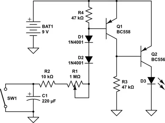
simulate this circuit – Schematic created using CircuitLab
The explanation the magazine gives for the circuit is such that when connected C1 charges up via current taken from R1, R2, D1, D2 and the base emitter junction of Q!. Because Q! is providing current to the charging capacitor no current flows through Q2. When the capacitor is fully charged no further current can be drawn from the components connected to it and so Q1 swictches off turning on Q2 and hence the LED or buzzer. closing SW1 restarts this process. I have connected this circuit up on a spring board and it only runs for 12 seconds, not 3.5 minutes (with maximum POT value of 1MΩ).
If I had a smartphone I would photograph the spring board but I have constructed more complicated projects on the board than this and so can't see how my connections could be wrong. I have even gone through with a multimeter testing the components and noted that the capacitor did charge up causing Q1 to switch off and Q2 to switch on only this was much quicker than 3.5 minutes. Any tips or hints?