I have question regarding the wiring of the output of PLC (mode: Omron CP1L). Below is the output wiring diagram.
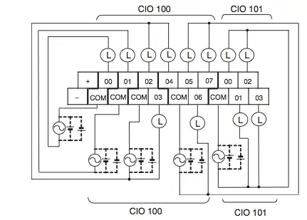
The PLC is AC powered, and input are 24 VDC. As the image shows, the output has a "+" and a "-" that supply a DC voltage. 00-07 are switches with separate COM. I have programmed to ladder logic correct to trigger an output on 01. But when I check with a multimeter across 01 and COM, I see no voltage at all.
What am I doing wrong? Does the output of 01 and COM actually supply a voltage? If not, what should I do? I cannot find it in the documentation.