4

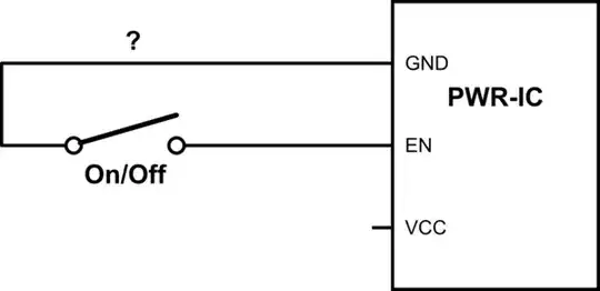
I have a circuit (below) where there's an IC responsible for battery charging, voltage boosting, power/regulation, etc. It has an "Enable" pin which is pulled up to VCC by default, and determines whether it supplies power or not. (High == ON, Low == OFF)

I want to hook this up to a toggle switch so that when the toggle is "open", the "Enable" pin is pulled down to ground. Is there a simple/easy way to wire this? I'd like to avoid adding any additional components if possible.

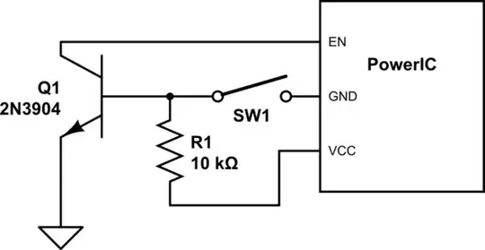
Right now I have the leads connected as below, which works but is confusing because it is the opposite of the switch's labeling. (Open-switch turns the system on and closed switch turns it off).

Thanks!

schematic

simulate this circuit – Schematic created using CircuitLab

Ismail Degani
  • 239
  • 2
  • 10
  • 3
    You can use a pull down resistor, but that would require a resistor. – zack1544 Jul 28 '16 at 01:06
  • 1
    Adding a resistor is ok, but how is it wired up? Remember, EN is internally pulled up. If I put the pulldown on the other side of the enable signal, now the pin is both internally pulled up and externally pulled down. This results in an ambiguous voltage, because I don't know the resistance of the internal pull-up. Should I play with it using small and smaller resistances until it works? Is there a cleaner way? – Ismail Degani Jul 28 '16 at 01:12
  • Why not simply relabel the swich? Or buy a switch that's labeled appropriately (or not labeled at all) for use here? – Jim Fischer Jul 28 '16 at 04:33
  • 1
    Yeah of course that's a possibility, but I was curious to see whether there was a clever trick to do it with the existing switch and its manufacturer-printed labeling. – Ismail Degani Jul 29 '16 at 22:45
  • Is this power IC a Powerboost from Adafruit, perchance? That's how I ended up here. – Clonkex Jan 30 '22 at 10:14

2 Answers2

4

One way is to use a transistor as an inverter, like so:

Please chime in if you've got a better solution!

schematic

simulate this circuit – Schematic created using CircuitLab

Ismail Degani
  • 239
  • 2
  • 10
  • I think this is too much effort for a such easy application. Some resistors may suffice – M.Ferru Jul 29 '16 at 23:36
  • 2
    I agree it is more complex, but it does waste less power than @transistor's solution. With just a 1k resistor between V+ and ground, my device (5V source) would be giving away 5mA, which is non-trivial for a 100mAh LiPo. In any case, why downvote a working solution? Come on guys! :) – Ismail Degani Aug 01 '16 at 23:34
3

schematic

simulate this circuit – Schematic created using CircuitLab

Figure 1. Inverting the enable logic.

  • Connect a milliammeter across the switch on your existing circuit and note the current to ground.
  • Calculate the value of the internal pull-up resistor: \$ R_{PU} = \frac {V_+}{I} \$.
  • Add a pull-down resistor of about one tenth the value of the pull-up. (Note 1.)
  • Rewire the switch to pull high.

Note that in this circuit R2 will consume a little extra power when the switch is closed.

Note 1. R2 will be fighting R1 in trying to pull the input low. Most digital logic families switching point is below half-supply. e.g., One would think that a 5 V logic input would read anything below 2.5 V as 'low'. This isn't the case and the thresholds are usually defined as a guaranteed low threshold and a guaranteed high threshold. A 10:1 pull-up / pull-down ratio should guarantee a zero when the switch is open.

Transistor
  • 175,532
  • 13
  • 190
  • 404