Are there any profits of using the first circuit for divider instead of the second one?
simulate this circuit – Schematic created using CircuitLab
Are there any profits of using the first circuit for divider instead of the second one?
simulate this circuit – Schematic created using CircuitLab
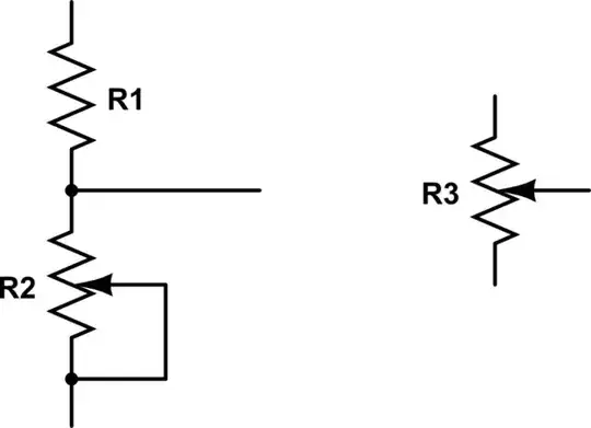
The circuit on the right will have the full range of the voltage connected. The circuit on the left will have the maximum given by the voltage divider of \$R_1\$ and \$R_2\$. This is if you want to limit the maximum voltage to a lower value than the maximum voltage in the circuit.
Yes: it has a different range. Depending on the application, that may be what you want.
The primary reason one does this (left hand side) in the real world is to prevent hazardous conditions from arising. In some pots if you move the wiper off of the end of the track it can short out or open circuit (it very much depends upon the construction).
Some op-amps don't want heir inputs being driven to the rail, so you'd put a series resistor in there to ensure that it always stay within the operational range of the op-amp input.
In some cases if the pot shorts you want to prevent high currents from running through the pot and collapsing the rail, over heating etc.
So yes, it can be bad and limit your range of operation, but it is primarily used to protect for faults.
Of course there are uses where it makes sense to only vary resistance between certain values. In that case it is not a problem.
Safety. A series resistor is connected so that the load resistance cannot become \$ 0\Omega\$.

simulate this circuit – Schematic created using CircuitLab
If you connect a load to the wiper of your pot, a portion of the pot (top) is in series with the load (wiper) and the remainder is in parallel with the load. As the pot is adjusted, Load Voltage varies from 0V to 12V.
But if you connect the wiper to one end of the pot, you effectively have a resistance which varies from 0\$\Omega\$ to rated resistance.
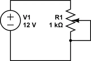
As you move the wiper to the top, the series resistance will decrease to \$ 0\Omega\$, which would mean \$\infty\$ current. So to protect the pot from burning up or overloading the source, a series resistance is added.
In your example, consider what the output would be:
In the first circuit, the output ranges from \$0 \Leftrightarrow(V-I_{R1}R1)\$
In the second circuit, the output ranges from \$0 \Leftrightarrow V\$
So, if you need a variable divider with some hard limits, external resistors are the way to go.