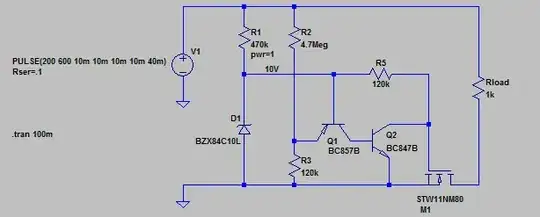
Honestly, I don't know if this circuit is appropriate for your specific needs as you didn't give much details, but just for fun, here is what I came up with. It must be located between the supposed diode bridge and the rest of the circuit to protect (it takes DC current as input).
Explanations
The D1+R1 part forms a small 10V supply (you may need an additional capacitor across D1). R2+R3 is a voltage divider. When the voltage divider output goes above 10V (which happens when the supply goes above ~400V), Q1 starts conducting, which in turn makes Q2 conduct and shuts down the mosfet. When the fault disappears, everything goes back to normal, but it takes a longer time.
There may be ways to make the circuit simpler. For example, you can eliminate Q2 by exchanging Q1 base and emitter, but in this case, it takes longer to shut down from the fault than to recover.
Component choice
You have to be careful on the choice of the mosfet. It has to withstand the maximum fault voltage you want to prevent. Also, R1 dissipation must be rated appropriately: 1W is the minimum, may be more, depending on the voltage you want to handle. Also use appropriate diodes for the bridge, they also should withstand the max fault voltage.
Operating conditions
Power consumption of this circuit under normal conditions is about 0.3 Watts.
Shutting down due to an overvoltage takes about 100µS. Recovering when the fault disappears takes about 400µS.
Edit
This is the source of the circuit, for reference
Version 4
SHEET 1 1012 700
WIRE 240 16 64 16
WIRE 384 16 240 16
WIRE 912 16 384 16
WIRE 240 64 240 16
WIRE 384 64 384 16
WIRE 64 144 64 16
WIRE 240 208 240 144
WIRE 320 208 240 208
WIRE 496 208 320 208
WIRE 592 208 496 208
WIRE 768 208 672 208
WIRE 912 208 912 16
WIRE 64 288 64 224
WIRE 240 336 240 208
WIRE 496 336 496 208
WIRE 768 352 768 208
WIRE 768 352 656 352
WIRE 384 400 384 144
WIRE 448 400 384 400
WIRE 592 400 544 400
WIRE 384 432 384 400
WIRE 768 480 768 352
WIRE 240 528 240 400
WIRE 240 528 64 528
WIRE 384 528 384 512
WIRE 384 528 240 528
WIRE 656 528 656 448
WIRE 656 528 384 528
WIRE 752 528 656 528
WIRE 912 528 912 288
WIRE 912 528 848 528
WIRE 64 576 64 528
FLAG 64 288 0
FLAG 64 576 0
FLAG 320 208 10V
SYMBOL voltage 64 128 R0
WINDOW 3 -489 44 Left 2
WINDOW 123 0 0 Left 2
WINDOW 39 -488 73 Left 2
SYMATTR InstName V1
SYMATTR Value PULSE(200 600 10m 10m 10m 10m 40m)
SYMATTR SpiceLine Rser=.1
SYMBOL nmos 848 480 R90
WINDOW 0 118 71 VRight 2
WINDOW 3 88 -22 VRight 2
SYMATTR InstName M1
SYMATTR Value STW11NM80
SYMBOL res 896 192 R0
SYMATTR InstName Rload
SYMATTR Value 1k
SYMBOL zener 256 400 R180
WINDOW 0 24 64 Left 2
WINDOW 3 24 0 Left 2
SYMATTR InstName D1
SYMATTR Value BZX84C10L
SYMATTR Description Diode
SYMATTR Type diode
SYMBOL res 224 48 R0
WINDOW 39 36 104 Left 2
SYMATTR InstName R1
SYMATTR Value 470k
SYMATTR SpiceLine pwr=1
SYMBOL res 368 48 R0
SYMATTR InstName R2
SYMATTR Value 2.2Meg
SYMBOL res 368 416 R0
SYMATTR InstName R3
SYMATTR Value 57k
SYMBOL pnp 544 336 R90
WINDOW 0 66 65 VLeft 2
WINDOW 3 93 63 VLeft 2
SYMATTR InstName Q1
SYMATTR Value BC857B
SYMBOL res 688 192 R90
WINDOW 0 0 56 VBottom 2
WINDOW 3 32 56 VTop 2
SYMATTR InstName R5
SYMATTR Value 57k
SYMBOL npn 592 352 R0
SYMATTR InstName Q2
SYMATTR Value BC847B
TEXT -426 382 Left 2 !.tran 100m
