A small (3.3V/10mA) uC circuit requires a ground. I designed the circuit’s PCB to use a nearby ground wire that is attached to the car’s frame in at least two places and used by the 2A windshield washer motor (other devices may use it as well). I created a break in the ground wire (denoted by A and B) and it is soldered to the PCB onto two pads nearly touching and connected by a 100 mil trace (2 oz), more than adequate for the washer motor. (The trace width calculator indicates 8 A conservatively.) Connecting the remaining ground wire C completes the uC circuit and everything works fine; the washer and the circuit. Both are on the same 12V supply but I’m curious if there is anything inherently wrong with this approach. Ideally, (from what I’ve read) I would add another separate ground wire for the uC circuit, but I would like to avoid adding another wire if at all possible. The uC is only controlling a relay. Should I isolate the A-B pads from the ground pour using a polygon cutout and then connect the uC circuit grounds to those pads with a single connection instead of having A and B directly connected to the ground pour? Does it matter?
There are numerous threads about connecting grounds, but the many I've read address noise and different voltage potentials; I have not seen anything that addresses sharing a ground with another higher-current circuit.
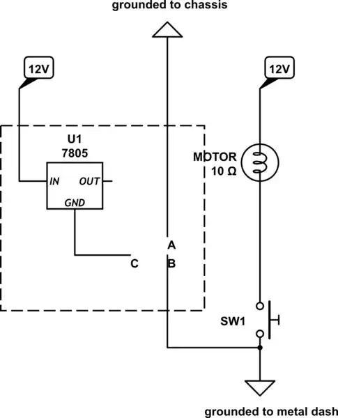
simulate this circuit – Schematic created using CircuitLab