0

I built a timer for my water heater and have a question about spark suppression. I am using a 120v house timer 1875W to operate a Packard (240B) 2 pole 40A 120v coil relay. The output of the relay contacts are connected to 240v that goes to the water heater element. It worked for about 3 months and then the relay does not release because I think the timer contacts are fused together supplying constant ac to the rly. coil. I think that I may need a spark suppressor across the input of the 120v input of the relay coil. I was thinking about a RC network but I don't know what type of cap and resistor values are needed. I have a drawing but I don't know how to upload it to this post.

Thanks, doogdoog
doogdoog
  • 1
  • 1
  • 2
    Can you try taking the timer "out-of-circuit" and see if you can get the relay(s) to open/close properly by powering them from, say, a light switch? If yes, then it's the timer; if not, the the relays are what welded. – Robherc KV5ROB Feb 09 '16 at 05:22
  • Yes, the problem is with the timer because when I unplug the timer, the relay releases. – doogdoog Feb 09 '16 at 20:31

2 Answers2

1

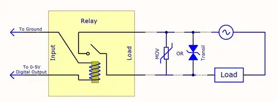
For spark suppression you can use a MOV (varistor) across the load terminals of the relay.

Relay spark suppression
(source: phidgets.com)

This will protect from high voltage spikes and prolong its life.

Glorfindel
  • 1,245
  • 3
  • 15
  • 20
Ignas Urba
  • 158
  • 5
  • I think this answer would be even better, personally, if it had a small "rule of thumb" to selecting a MOV, such as "don't go to close to the Vpeak of the mains voltage". Otherwise the OP may burn through them from cumulative degradation caused by small spikes with an opened relay. – Asmyldof Feb 09 '16 at 15:00
  • The timer contacts which feed the relay the 120v are the problem because I think that it is caused by the relay coil when it collapses. Won't the MOV be better on the input side of the coil? The input side is where the timer contacts are and is being fused by the collapsing of the relay coil. What value would the MOV have to be? – doogdoog Feb 09 '16 at 20:31
  • OP is using a 120VAC "wall plug" timer, not 5VDC digital logic. Also, OP's problem is as likely Inrush Current induced contact welding (his "load" is a pair of relays, so a purely inductive load), as it is by pull-out arcing. – Robherc KV5ROB Feb 09 '16 at 20:37
0

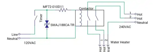
I think this circuit should work to protect your timer from inrush-current surges, and from pull-out sparks. That way, hopefully, you'll be protected from welding your contacts either way.

Protection Parts

Parts:

  • MF72-010D11
    "Inrush Current Limiter" - This resistor limits the initial surge current that can sometimes weld together contacts as induction motors, or relay coils, first start moving & take incredibly high currents.
  • SMAJ188CA-TR
    "Transil"/TVS Diode - This is basically 2 209V Zener diodes, wired "back-to-back" in 1 piece. It allows any voltages that spike over it's ~209V threshold to pass through itself, rather than arcing across the contacts of your timer switch.
Robherc KV5ROB
  • 5,108
  • 1
  • 11
  • 24
  • Yes, this looks like what I need since it is across the coil of the relay. How did you calculate what TVS diode and value to use? What is the MF72-010D11 and is the resistor part of the suppression protection? I did a search on the MF72-010D11 and didn't have any hits. – doogdoog Feb 10 '16 at 01:36
  • Both parts are readily available on http://www.digikey.com ...that's where I found the parts to spec for your circuit. The TVS diode I selected to have a higher minimum avalanche voltage above the max. 'normal' AC peak voltage of 170V-180V on a 120VAC line. That way it's unlikely for the transil to burn itself out on normal mains input. The resistor is an "Inrush Current Limiter" that presents a ~5ohm load when the timer first switches 'on', but then rapidly reduces resistance & allows the relay to take over. Without it, some coils can actually 'spot-weld' the contacts in your timer together. – Robherc KV5ROB Feb 10 '16 at 01:52
  • part links added to answer (below diagram) – Robherc KV5ROB Feb 10 '16 at 01:56
  • Hello Robherc, I looked at the digikey site and it showed 3 different digikey part numbers for the SMAJ188ca-TR: 497-7891-2-nd,1-nd and 6-nd. Which one should I choose? How do I connect to this part? I don't see any leads, so do I solder on the leads? Thanks – doogdoog Feb 10 '16 at 05:01
  • @doogdoog the -2-nd a d -6-nd digikey part numbers are for "reels" of parts. One is for a reel of 1000, and the other is for a custom-made (and higher cost) reel. Both are only useful if you're planning to use 500+ of them, or if you have a robotic assembly line; the -1-nd (linked @ bottom of answer post) is for ordering small(er than 1000) quantities. The SMAJ is a 'surface-mount' part; you 'tin' the pads on your pcb that you'll attach it to, then hold it down gently as you re-melt the solder on each pad to solder it down (It'll be small, probably on the order of maybe 1/8"x1/16"). – Robherc KV5ROB Feb 10 '16 at 05:53
  • Hello Robherc, I received the two items I bought from Digikey and the TVS diode is like you described and do you have any other suggestion on how to attach a wire to the diode? I almost lost it when it fell on the floor and very hard to handle. What kind of pcb board do you recommend and will that tiny thing handle the 120 plus volts? – doogdoog Feb 12 '16 at 22:01
  • @doogdoog believe it or not, that tiny little diode is rated to 'hold off' (reliably not avalanche' 188VAC, and is intended to reliably avalanche/'clamp' on 209VAC. Any pcb you can inexpensively source should work. A perfboard with copper pads/lines (NOT 'rings, they're often too spaced apart) around each hole is very convenient for 'one-off' custom designs. Here's one similar to a few boards I've used before (quick google search found it): http://www.allelectronics.com/make-a-store/item/sb-2h1/two-hole-pad-single-sided-breadboard/1.html – Robherc KV5ROB Feb 12 '16 at 22:59
  • For soldering tiny SMD components, I tin the copper pads I'm going to attach them to with a bit of solder first, then apply a light coating of petroleum-based flux over the tinned traces. The light coating of flux helps 'stick' the component in place while you get it in place, then hold it down with a pair of fine tweezers while you heat/melt one solder pool (the tinning you laid down earlier), then the other, with the tip of your soldering iron. The keys are patience & steadying your hands. Don't get in a hurry; brace your hands on something firm ("helping hands" are GREAT); then solder. :) – Robherc KV5ROB Feb 12 '16 at 23:05
  • Thanks, I didn't know they had pcb board with lines since the ones that I saw was either all copper plated or with holes. I'll see if radio shack has some tomorrow and does the diode run hot? The reason I am asking is because I intend to tape up the whole assemble and was wondering if it needs air cooling. – doogdoog Feb 13 '16 at 08:31
  • The ones I bought before were from Radio shack, sl that should work for you. As for the diode, it should only be conducting any current for a tiny fractiion of a second, right after the timer 'kicks off,' so I highly doubt it will need cooling. I'm not completely sure on the ICL resistor; but just running the coil(s) for your bigger relay/contactor, I doubt it'll heat up very significantly. – Robherc KV5ROB Feb 13 '16 at 13:35