1

Studied EE, haven't used it in 10 years, so pretty rusty.

Part 1: the board and how it's connected

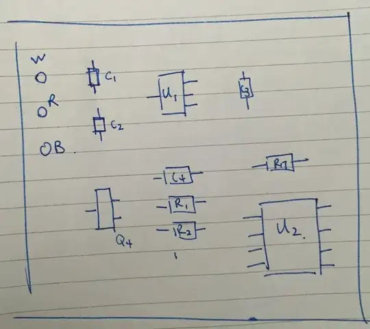
I'm looking at a very simple current controller that drives 3 different current levels based on a switch. Here's what the board looks like on the back,

enter image description here

On the left side, the "W" is the ground to the battery, "R" is the power, which is 7.5V, and the "B" is connected to the load - I'll explain this later.

The other side of this board is just 4 sets of resistors & LEDs that light up to show which setting you're on. No need to draw those.

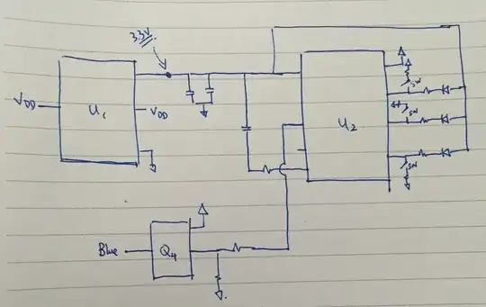
Here's a picture of how it's connected (more or less), and I'm confused about exactly how U2 works.

enter image description here

Of course they scratched off all the markings on the ICs so we'd have to guess what they are.

Part 2: my take on this board

Here's my guess,

  • U1 is a voltage reference, it's always at 3.3V even when the battery's voltage fluctuates.
  • U2 is an op-amp of sorts, but this is where I'm not sure because of all the weird connections.
  • Q4 is a MOSFET that drives current.

So it should be pretty simple, it's an op-amp that feeds in a variable voltage into the gate of the MOSFET that drives a variable current.

If I were to design my own current driver based on what's on this board, it'd probably look something like this,

enter image description here

This is pretty simple, got an op-amp with a negative feedback circuit. You put a switch on the positive+ input of the op-amp that switches between different sets of resistors and you get different sets of voltages on the output depending on the gain, which then drives the MOSFET.

"W" would be ground, "R" would be the 7.5V above the load, "B" would be the point below the load at the drain of the MOSFET.

Part 3: what I'm confused about

What exactly is U2?

Here's what I do know.

  • It has 8 pins, OK.
  • Top-left pin is power, 3.3V. Top-right pin is ground, OK.
  • Second-left pin is output, feeds right into the gate of the MOSFET
    (Q4), OK.
  • Second / Third / Fourth pin on the right side toggles between the 3 current settings. For any one setting, one of these pins is at one of three voltages (0.37V, 0.15V, 0.19V), and the other two are at 3.3V - just open-circuits.
  • The last two pins on the left do not seem to do anything or really connected to anything that matters.

What is U2? Why does it have no feedback? Maybe it's not an op-amp IC at all?

Part 4: my 2 questions

  1. What is U2?
  2. Is the circuit I created (the third image) basically right?

Thank you!!!

ADDITIONS

Sorry for not posting the actual photos.

Here's the back side (with all the ICs):

enter image description here

Here's the front, with the big switch button in the middle, and 3 sets of 4 resistor+LED combinations each.
enter image description here

reedvoid
  • 113
  • 5
  • 4
    Did you once try to reverse engineer your camera and broke it in the process? – Andy aka Jan 19 '16 at 14:28
  • Posted photos, sorry, newbie mistake. – reedvoid Jan 19 '16 at 14:39
  • How does the 1 switch toggle all three inputs to U2? Your schematics are missing something... – SpaceCowboyMDK Jan 19 '16 at 14:44
  • @SpaceCowboyMDK probably didn't draw it right, I don't know how how the switch works but it probably is switching between 3 different points on the board that have 3 sets of resistor+LED combinations. – reedvoid Jan 19 '16 at 14:50
  • Focused images of a clean board with a resolution that is not from the 90s would have probably been better... – PlasmaHH Jan 19 '16 at 14:57
  • @PlasmaHH well it's on an iPhone 6, it's zoomed in b/c the focal length is pretty long on that little lens so I can't put the board right next to the camera, so had to take it from further away with a digital zoom, hence the blurriness (that's my theory anyway). – reedvoid Jan 19 '16 at 15:02

3 Answers3

5

It's a small microcontroller. The pins on the right are the user interface (pushbuttons and LEDs sharing the same pins), and the connection to the MOSFET is a PWM output.

Dave Tweed
  • 172,781
  • 17
  • 234
  • 402
  • If it is a microcontroller, it is one with 3 ADCs and 1 DAC (for the variable components). It would also have to be programmed before being soldered onto the board as there is no programming header. – SpaceCowboyMDK Jan 19 '16 at 14:40
  • Posted photos. Could you provide a link to any such microcontroller? As in it's a digital circuit, not an analog one? – reedvoid Jan 19 '16 at 14:40
  • Pretty much all of the microcontroller manufacturers have 8-pin variants. Just go to their product selection page and index on that. If you can't at least identify a specific manufacturer, it's pointless to speculate. Yes, it's mostly digital, although the output to the MOSFET might be analog. I guess it would be more properly be called a "mixed signal" device. – Dave Tweed Jan 19 '16 at 14:52
  • Why would someone use a microcontroller instead of a simple op-amp? What's the advantage in that? Seems like an op-amp would be way simpler. – reedvoid Jan 19 '16 at 14:53
  • An opamp can be part of a current source, but providing the user interface that allows you to switch current levels based on a simple momentary pushbutton is most easily (and cheaply) done with a microcontroller. – Dave Tweed Jan 19 '16 at 14:55
  • @SpaceCowboyMDK: There's no reason for it to have ADCs, since there doesn't seem to be any feedback involved. And yes, it's likely that it would be gang (or mask) programmed before assembly. However, small, cheap PCBs like these are built as large panels and then broken apart after assembly. Sometimes the programming interface is built into the panel. – Dave Tweed Jan 19 '16 at 15:01
  • 1
    Anything that uses a momentary pushbutton to select modes is probably a microcontroller or an ASIC. – Spehro Pefhany Jan 19 '16 at 15:44
  • @SpehroPefhany Actually that's a really good point... I didn't even think about the timing of the button push. Looks like this ain't gonna be done with an op-amp after all, need some ASIC. – reedvoid Jan 24 '16 at 01:18
1

A photo would be worth a lot here. My initial guess that U1 is a voltage regulator and U2 is an 8-pin microcontroller (PWM control).

Spehro Pefhany
  • 397,265
  • 22
  • 337
  • 893
0

It sounds like it is an ASIC (application specific IC) that has a resistor ladder (R-2R ladder network) built into it with a buffered output. See link below.

https://en.wikipedia.org/wiki/Resistor_ladder

What is your end goal? To buy another IC or to build another current driver? Some things are easier to engineer anew rather than reverse engineer.

SpaceCowboyMDK
  • 375
  • 1
  • 7
  • The goal is to make my own current driver, but (as you can clearly see) I don't have any practical experience I wanted to be sure not to screw it up, so trying to figure out what exactly this existing circuit is. – reedvoid Jan 19 '16 at 14:51
  • It sounds like you have all the experience you need to implement this circuit replacing U2 with an op amp and a R-2R circuit. Use LTSpice to simulate it first and increase your confidence before building. – SpaceCowboyMDK Jan 19 '16 at 17:02