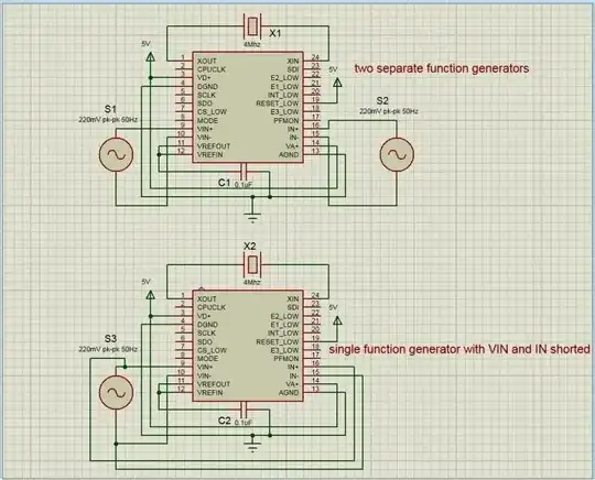
I am using CS5463 for energy metering application. Is there any way to check if IC is working properly without communicating with the IC through SPI interface? I just want to make sure that the connections are right before programming the controller.
Asked
Active
Viewed 708 times
1
-
Link to the data sheet? – Andy aka Nov 30 '15 at 10:26
-
http://www.cirrus.com/en/mobile/pubs/proDatasheet/CS5463_F3.pdf – Khurram Nov 30 '15 at 10:37
-
Run round with a voltmeter on all the power pins and input pins and report the findings back here I guess. – Andy aka Nov 30 '15 at 11:06
-
Va+ and Vd+ 5V. GDN – Khurram Nov 30 '15 at 11:24
-
VA+ and VD+ 5V. AGND and DGND 0V. Voltage and current channels 150mV pk-pk. I viewed the E1 pin on oscilloscope which showed 5v DC. I was was expecting a square wave. – Khurram Nov 30 '15 at 11:29
-
If there is no ac connected to the inputs then E1 won't do anything I reckon. – Andy aka Nov 30 '15 at 11:59
2 Answers
1
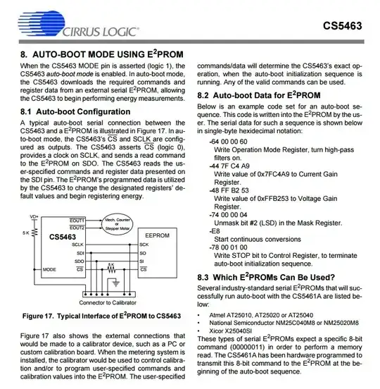
The IC has an “Auto-boot” Mode which allows setup from a serial E2PROM'. This does not meet the letter of your exact requirement but probably meets the spirit of it.
Page 40 of the data sheet provides detailed instructions of how to use this mode and what data to put in the EEPROM for a basic test setup - see below. A 21 byte sequence is required.
Russell McMahon
- 150,303
- 18
- 213
- 391
-
The datasheet gives default values for registers k has value 1 by default and N=4000. Datasheet says the default value are loaded on reset. So I guess without any calibration we should se square wave on its E1 pin since 'k' and N are the values that determine its frequency. But I am getting DC 5V on oscilloscope. Am I thinking in the right direction? – Khurram Dec 01 '15 at 06:52
-
@Khurram You should read ALL comments and seek to understand what they mean. 21 hours ago Andy said "If there is no ac connected to the inputs then E1 won't do anything I reckon." That seems reasonably likely. You MAY have to produce simulated I & V input signals. This is not very hard AND noise input from a wire in an AC mains environment may be enoughy. Or the IC MAY respond to DC which makes it even easier - the data sheet should tell you. – Russell McMahon Dec 01 '15 at 09:29
-
Sorry I did not mentioned that I used two separate function generators to produce simulated I and V(both being 200mV pk-pk) input signals and observed the resulting output on oscilloscope which was 5V DC. Today I used a single function generator and shorted current and voltage channels. The result is the same. – Khurram Dec 01 '15 at 09:59
-
@Khurram It helps to know what you are doing when you get a given result :-). | Can you provide the ACTUAL circut of you test setup? Quite oftenpeople say "the same as xxx" or "just like xxx or ..., and it more often than not happens that what they are doing is different or very different to the cct they refer to. Word pictures are a less satisfactory way of doing this unless they are "drwan" with great care and detail - and even thena diagram usually helps. – Russell McMahon Dec 01 '15 at 11:15

